Knowledge
- Explain DRS / storage DRS affinity and anti-affinity rules
- Identify required hardware components to support DPM
- Identify EVC requirements, baselines and components
- Understand the DRS / storage DRS migration algorithms, the Load Imbalance Metrics, and their impact on migration recommendations
Skills and Abilities
- Properly configure BIOS and management settings to support DPM
- Test DPM to verify proper configuration
- Configure appropriate DPM Threshold to meet business requirements
- Configure EVC using appropriate baseline
- Change the EVC mode on an existing DRS cluster
- Create DRS and DPM alarms
- Configure applicable power management settings for ESXi hosts
- Properly size virtual machines and clusters for optimal DRS efficiency
- Properly apply virtual machine automation levels based upon application requirements
- Create and administer ESXi host and Datastore Clusters
- Administer DRS / Storage DRS
Properly configure BIOS and management settings to support DPM
Official Documentation:
vSphere Resource Management Guide, Chapter 10 “Using DRS Clusters to Manage Resources”, Section “Managing Power Resources”, page 67.
The vSphere Distributed Power Management (DPM) feature allows a DRS cluster to reduce its power consumption by powering hosts on and off based on cluster resource utilization.
vSphere DPM monitors the cumulative demand of all virtual machines in the cluster for memory and CPU resources and compares this to the total available resource capacity of all hosts in the cluster. If sufficient excess capacity is found, vSphere DPM places one or more hosts in standby mode and powers them off after migrating their virtual machines to other hosts. Conversely, when capacity is deemed to be inadequate, DRS brings hosts out of standby mode (powers them on) and uses vMotion to migrate virtual machines to them. When making these calculations, vSphere DPM considers not only current demand, but it also honors any user-specified virtual machine resource reservations.
NOTE ESXi hosts cannot automatically be brought out of standby mode unless they are running in a cluster managed by vCenter Server.
vSphere DPM can use one of three power management protocols to bring a host out of standby mode:
Intelligent Platform Management Interface (IPMI), Hewlett-Packard Integrated Lights-Out (iLO), or Wake-On-LAN (WOL). Each protocol requires its own hardware support and configuration. If a host does not support any of these protocols it cannot be put into standby mode by vSphere DPM. If a host supports multiple protocols, they are used in the following order: IPMI, iLO, WOL.
NOTE Do not disconnect a host in standby mode or move it out of the DRS cluster without first powering it on, otherwise vCenter Server is not able to power the host back on.
Configure IPMI or iLO Settings for vSphere DPM
IPMI is a hardware-level specification and Hewlett-Packard iLO is an embedded server management technology. Each of them describes and provides an interface for remotely monitoring and controlling computers.
You must perform the following procedure on each host.
Prerequisites
Both IPMI and iLO require a hardware Baseboard Management Controller (BMC) to provide a gateway for accessing hardware control functions, and allow the interface to be accessed from a remote system using serial or LAN connections. The BMC is powered-on even when the host itself is powered-off. If properly enabled, the BMC can respond to remote power-on commands.
If you plan to use IPMI or iLO as a wake protocol, you must configure the BMC. BMC configuration steps vary according to model. See your vendor’s documentation for more information. With IPMI, you must also ensure that the BMC LAN channel is configured to be always available and to allow operator-privileged commands.
On some IPMI systems, when you enable “IPMI over LAN” you must configure this in the BIOS and specify a particular IPMI account.
vSphere DPM using only IPMI supports MD5- and plaintext-based authentication, but MD2-based authentication is not supported. vCenter Server uses MD5 if a host’s BMC reports that it is supported and enabled for the Operator role. Otherwise, plaintext-based authentication is used if the BMC reports it is supported and enabled. If neither MD5 nor plaintext authentication is enabled, IPMI cannot be used with the host and vCenter Server attempts to use Wake-on-LAN.
Procedure
- Select the host in the vSphere Client inventory.
- Click the Configuration tab.
- Click Power Management.
- Click Properties.
-
Enter the following information.
- User name and password for a BMC account. (The user name must have the ability to remotely power the host on.)
- IP address of the NIC associated with the BMC, as distinct from the IP address of the host. The IP address should be static or a DHCP address with infinite lease.
- MAC address of the NIC associated with the BMC.
- User name and password for a BMC account. (The user name must have the ability to remotely power the host on.)
- Click OK.
Enabling vSphere DPM for a DRS Cluster
After you have performed configuration or testing steps required by the wake protocol you are using on each host, you can enable vSphere DPM.
Configure the power management automation level, threshold, and host-level overrides. These settings are configured under Power Management in the cluster’s Settings dialog box.
You can also create scheduled tasks to enable and disable DPM for a cluster using the Schedule Task: Change Cluster Power Settings wizard.
NOTE If a host in your DRS cluster has USB devices connected, disable DPM for that host. Otherwise, DPM might turn off the host and sever the connection between the device and the virtual machine that was using it.
Automation Level
Whether the host power state and migration recommendations generated by vSphere DPM are executed automatically or not depends upon the power management automation level selected for the feature.
The automation level is configured under Power Management in the cluster’s Settings dialog box.
NOTE The power management automation level is not the same as the DRS automation level.
| Option | Description |
| Off | The feature is disabled and no recommendations will be made. |
| Manual | Host power operation and related virtual machine migration recommendations are made, butnot automatically executed. These recommendations appear on the cluster’s DRS tab in thevSphere Client. |
| Automatic | Host power operations are automatically executed if related virtual machine migrations can allbe executed automatically. |
vSphere DPM Threshold
The power state (host power on or off) recommendations generated by the vSphere DPM feature are assigned priorities that range from priority-one recommendations to priority-five recommendations.
These priority ratings are based on the amount of over- or under-utilization found in the DRS cluster and the improvement that is expected from the intended host power state change. A priority-one recommendation is mandatory, while a priority-five recommendation brings only slight improvement.
The threshold is configured under Power Management in the cluster’s Settings dialog box. Each level you move the vSphere DPM Threshold slider to the right allows the inclusion of one more lower level of priority in the set of recommendations that are executed automatically or appear as recommendations to be manually executed. At the Conservative setting, vSphere DPM only generates priority-one recommendations, the next level to the right only priority-two and higher, and so on, down to the Aggressive level which generates priority-five recommendations and higher (that is, all recommendations.)
NOTE The DRS threshold and the vSphere DPM threshold are essentially independent. You can differentiate the aggressiveness of the migration and host-power-state recommendations they respectively provide.
Host-Level Overrides
When you enable vSphere DPM in a DRS cluster, by default all hosts in the cluster inherit its vSphere DPM automation level.
You can override this default for an individual host by selecting the Host Options page of the cluster’s Settings dialog box and clicking its Power Management setting. You can change this setting to the following options:
- Disabled
- Manual
- Automatic
NOTE Do not change a host’s Power Management setting if it has been set to Disabled due to failed exit standby mode testing.
After enabling and running vSphere DPM, you can verify that it is functioning properly by viewing each host’s Last Time Exited Standby information displayed on the Host Options page in the cluster Settings dialog box and on the Hosts tab for each cluster. This field shows a timestamp and whether vCenter Server Succeeded or Failed the last time it attempted to bring the host out of standby mode. If no such attempt has been made, the field displays Never.
NOTE Times for the Last Time Exited Standby text box are derived from the vCenter Server event log. If this log is cleared, the times are reset to Never.
Monitoring vSphere DPM
You can use event-based alarms in vCenter Server to monitor vSphere DPM.
The most serious potential error you face when using vSphere DPM is the failure of a host to exit standby mode when its capacity is needed by the DRS cluster. You can monitor for instances when this error occurs by using the preconfigured Exit Standby Error alarm in vCenter Server. If vSphere DPM cannot bring a host out of standby mode (vCenter Server event DrsExitStandbyModeFailedEvent), you can configure this alarm to send an alert email to the administrator or to send notification using an SNMP trap. By default, this alarm is cleared after vCenter Server is able to successfully connect to that host.
To monitor vSphere DPM activity, you can also create alarms for the following vCenter Server events.
| Event Type | Event Name |
| Entering Standby mode (about to power off host) | DrsEnteringStandbyModeEvent |
| Successfully entered Standby mode (host power off succeeded) | DrsEnteredStandbyModeEvent |
| Exiting Standby mode (about to power on the host) | DrsExitingStandbyModeEvent |
| Successfully exited Standby mode (power on succeeded) | DrsExitedStandbyModeEvent |
For more information about creating and editing alarms, see the vSphere Monitoring and Performance documentation.
If you use monitoring software other than vCenter Server, and that software triggers alarms when physical hosts are powered off unexpectedly, you might have a situation where false alarms are generated when vSphere DPM places a host into standby mode. If you do not want to receive such alarms, work with your vendor to deploy a version of the monitoring software that is integrated with vCenter Server. You could also use vCenter Server itself as your monitoring solution, because starting with vSphere 4.x, it is inherently aware of vSphere DPM and does not trigger these false alarms.
Test DPM to verify proper configuration
Official Documentation:
vSphere Resource Management Guide, Chapter 10 “Using DRS Clusters to Manage Resources”, Section “Test Wake-on-LAN for vSphere DPM”, page 68.
See previous objective.
Configure appropriate DPM Threshold to meet business requirements
Official Documentation:
vSphere Resource Management Guide, Chapter 10 “Using DRS Clusters to Manage Resources”, Section “Test Wake-on-LAN for vSphere DPM”, page 69.
See first objective.
Configure EVC using appropriate baseline
Official Documentation:
vCenter Server Host Management Guide, Chapter 12, “Migrating Virtual Machines”, Section “CPU Compatibility and EVC” and further, page 121.
CPU Compatibility and EVC
vCenter Server performs a number of compatibility checks before allowing migration of running or suspended virtual machines to ensure that the virtual machine is compatible with the target host.
vMotion transfers the running state of a virtual machine between underlying ESXi systems. Successful live migration requires that the processors of the target host be able to provide the same instructions to the virtual machine after migration that the processors of the source host provided before migration. Clock speed, cache size, and number of cores can differ between source and target processors, but the processors must come from the same vendor class (AMD or Intel) to be vMotion compatible.
Migrations of suspended virtual machines also require that the virtual machine be able to resume execution on the target host using equivalent instructions.
When you initiate a migration with vMotion or a migration of a suspended virtual machine, the Migrate Virtual Machine wizard checks the destination host for compatibility and produces an error message if there are compatibility problems that will prevent migration.
The CPU instruction set available to the operating system and applications running in a virtual machine is determined at the time that a virtual machine is powered on. This CPU “feature set” is determined based on the following items:
- Host CPU family and model
- Settings in the BIOS that might disable CPU features
- The ESX/ESXi version running on the host
- The virtual machine’s virtual hardware version
- The virtual machine’s guest operating system
To improve CPU compatibility between hosts of varying CPU feature sets, some host CPU features can be “hidden” from the virtual machine by placing the host in an Enhanced vMotion Compatibility (EVC) cluster.
NOTE Host CPU features can also be hidden from a virtual machine by applying a custom CPU compatibility mask to the virtual machine, but this is not recommended. VMware, in partnership with CPU and hardware vendors, is working to maintain vMotion compatibility across the widest range of processors. For additional information, search the VMware Knowledge Base for the vMotion and CPU Compatibility FAQ.
CPU Compatibility Scenarios
vCenter Server’s CPU compatibility checks compare the CPU features available on the source host, the subset of features that the virtual machine can access, and the features available on the target host. Without the use of EVC, any mismatch between two hosts’ user-level features will block migration, whether or not the virtual machine itself has access to those features. A mismatch between two hosts’ kernel-level features, however, blocks migration only when the virtual machine has access to a feature that the target host does not provide.
User-level features are non-privileged instructions that might be used by virtual machine applications. These include SSE3, SSSE3, SSE4.1, SSE4.2, and AES. Because they are user-level instructions that bypass the virtualization layer, these instructions could cause application instability if mismatched after a migration with vMotion.
Kernel-level features are privileged instructions that might be used by the virtual machine operating system.
These include the AMD No eXecute (NX) and the Intel eXecute Disable (XD) security features.
When you attempt to migrate a virtual machine with vMotion, one of the following scenarios applies:
- The destination host feature set matches the virtual machine’s CPU feature set. CPU compatibility requirements are met, and migration with vMotion proceeds.
- The virtual machine’s CPU feature set contains features not supported by the destination host. CPU compatibility requirements are not met, and migration with vMotion cannot proceed.
NOTE EVC overcomes such incompatibility by providing a “baseline” feature set for all virtual machines running in a cluster and that hides the differences among the clustered hosts’ CPUs from the virtual machines.
- The destination host supports the virtual machine’s feature set, plus additional user-level features (such as SSE4.1) not found in the virtual machine’s feature set. CPU compatibility requirements are not met, and migration with vMotion cannot proceed.
NOTE This type of incompatibility is ignored for migrations among hosts in EVC clusters.
- The destination host supports the virtual machine’s feature set, plus additional kernel-level features (such as NX or XD) not found in the virtual machine’s feature set. CPU compatibility requirements are met, and migration with vMotion proceeds. The virtual machine retains its CPU feature set as long as it remains powered on, allowing it to migrate freely back to the original host. However, if the virtual machine is rebooted, it acquires a new feature set from the new host, which might cause vMotion incompatibility if you attempt to migrate the virtual machine back to the original host.
CPU Families and Feature Sets
Processors are grouped into families. Processors within a given family generally have similar feature sets.
Processor families are defined by the processor vendors. You can distinguish different processor versions within the same family by comparing the processors’ model, stepping level, and extended features. In some cases, processor vendors have introduced significant architectural changes within the same processor family, such as the SSSE3 and SSE4.1 instructions, and NX/XD CPU security features.
By default, vCenter Server identifies mismatches on features accessible to applications as incompatible to guarantee the stability of virtual machines after migrations with vMotion.
Server hardware’s CPU specifications will usually indicate whether or not the CPUs contain the features that affect vMotion compatibility.
For more information on identifying Intel processors and their features, see Application Note 485: Intel® Processor Identification and the CPUID Instruction, available from Intel. For more information on identifying AMD processors and their features, see CPUID Specification, available from AMD.
About Enhanced vMotion Compatibility
You can use the Enhanced vMotion Compatibility (EVC) feature to help ensure vMotion compatibility for the hosts in a cluster. EVC ensures that all hosts in a cluster present the same CPU feature set to virtual machines, even if the actual CPUs on the hosts differ. Using EVC prevents migrations with vMotion from failing because of incompatible CPUs.
Configure EVC from the cluster settings dialog box. When you configure EVC, you configure all host processors in the cluster to present the feature set of a baseline processor. This baseline feature set is called the EVC mode. EVC leverages AMD-V Extended Migration technology (for AMD hosts) and Intel FlexMigration technology (for Intel hosts) to mask processor features so that hosts can present the feature set of an earlier generation of processors. The EVC mode must be equivalent to, or a subset of, the feature set of the host with the smallest feature set in the cluster.
EVC masks only those processor features that affect vMotion compatibility. Enabling EVC does not prevent a virtual machine from taking advantage of faster processor speeds, increased numbers of CPU cores, or hardware virtualization support that might be available on newer hosts.
EVC cannot prevent virtual machines from accessing hidden CPU features in all circumstances. Applications that do not follow CPU vendor recommended methods of feature detection might behave unexpectedly in an EVC environment. VMware EVC cannot be supported with ill-behaved applications that do not follow the CPU vendor recommendations. For more information about creating well-behaved applications, search the VMware Knowledge Base for the article Detecting and Using New Features in CPUs.
EVC Requirements
Hosts in an EVC cluster must meet certain requirements.
To enable EVC on a cluster, the cluster must meet the following requirements:
- All virtual machines in the cluster that are running on hosts with a feature set greater than the EVC mode you intend to enable must be powered off or migrated out of the cluster before EVC is enabled.
- All hosts in the cluster must have CPUs from a single vendor, either AMD or Intel.
- All hosts in the cluster must be running ESX/ESXi 3.5 Update 2 or later.
- All hosts in the cluster must be connected to the vCenter Server system.
- All hosts in the cluster must have advanced CPU features, such as hardware virtualization support (AMDV or Intel VT) and AMD No eXecute (NX) or Intel eXecute Disable (XD), enabled in the BIOS if they are available.
- All hosts in the cluster should be configured for vMotion. See “Host Configuration for vMotion,” on page 117.
- All hosts in the cluster must have supported CPUs for the EVC mode you want to enable. To check EVC support for a specific processor or server model, see the VMware Compatibility Guide at http://www.vmware.com/resources/compatibility/search.php.
Any host added to an existing EVC-enabled cluster must also meet the requirements
NOTE Hardware vendors sometimes disable particular CPU features in the BIOS by default. This can cause problems in enabling EVC, because the EVC compatibility checks detect the absence of features that are expected to be present for a particular CPU. If you cannot enable EVC on a system with a compatible processor, ensure that all features are enabled in the BIOS.
Create an EVC Cluster
Create an EVC cluster to help ensure vMotion compatibility between the hosts in the cluster.
When you create an EVC cluster, use one of the following methods:
- Create an empty cluster, enable EVC, and move hosts into the cluster.
- Enable EVC on an existing cluster.
VMware recommends creating an empty EVC cluster as the simplest way of creating an EVC cluster with minimal disruption to your existing infrastructure.
Prerequisites
Before you create an EVC cluster, ensure that the hosts you intend to add to the cluster meet the requirements listed in “EVC Requirements,” on page 123.
Procedure
- Create an empty cluster, and enable EVC.
Select the CPU vendor and EVC mode appropriate for the hosts you intend to add to the cluster. For information on configuring EVC, see the vSphere Client online Help.
Other cluster features such as vSphere DRS and vSphere HA are fully compatible with EVC. You can enable these features when you create the cluster. For information on specific cluster options, see the vSphere Client online Help.
- Select a host to move into the cluster.
-
If the host feature set is greater than the EVC mode that you have enabled for the EVC cluster, ensure that the cluster has no powered-on virtual machines.
- Power off all the virtual machines on the host.
- Migrate the host’s virtual machines to another host using vMotion.
- Power off all the virtual machines on the host.
- Move the host into the cluster.
You can power on the virtual machines on the host, or migrate virtual machines into the cluster with vMotion, if the virtual machines meet CPU compatibility requirements for the cluster’s EVC mode. Virtual machines running on hosts with more features than the EVC mode must be powered off before migration into the cluster.
- Repeat Step 3 and Step 4 for each additional host that you want to move into the cluster.
Enable EVC on an Existing Cluster
Enable EVC on an existing cluster to help ensure vMotion compatibility between the hosts in the cluster.
Prerequisites
Before you enable EVC on an existing cluster, ensure that the hosts in the cluster meet the requirements listed in “EVC Requirements,” on page 123.
Procedure
- Select the cluster for which you want to enable EVC.
-
If virtual machines are running on hosts that have feature sets greater than the EVC mode you intend to enable, ensure that the cluster has no powered-on virtual machines.
- Power off all the virtual machines on the hosts with feature sets greater than the EVC mode
- Migrate the cluster’s virtual machines to another host using vMotion.
Because these virtual machines are running with more features than the EVC mode you intend to set, power off the virtual machines to migrate them back into the cluster after enabling EVC.
- Power off all the virtual machines on the hosts with feature sets greater than the EVC mode
- Ensure that the cluster contains hosts with CPUs from only one vendor, either Intel or AMD.
- Edit the cluster settings and enable EVC.
Select the CPU vendor and feature set appropriate for the hosts in the cluster.
- If you powered off or migrated virtual machines out of the cluster, power on the virtual machines in the cluster, or migrate virtual machines into the cluster.
Any virtual machines running with a larger feature set than the EVC mode you enabled for the cluster must be powered off before they can be moved back into the cluster.
Change the EVC Mode for a Cluster
If all the hosts in a cluster are compatible with the new mode, you can change the EVC mode of an existing EVC cluster. You can raise the EVC mode to expose more CPU features, or lower the EVC mode to hide CPU features and increase compatibility.
To raise the EVC mode from a CPU baseline with fewer features to one with more features, you do not need to turn off any running virtual machines in the cluster. Virtual machines that are running do not have access to the new features available in the new EVC mode until they are powered off and powered back on. A full power cycling is required. Rebooting the guest operating system or suspending and resuming the virtual machine is not sufficient.
To lower the EVC mode from a CPU baseline with more features to one with fewer features, you must first power off any virtual machines in the cluster that are running at a higher EVC mode than the one you intend to enable, and power them back on after the new mode has been enabled.
Prerequisites
If you intend to lower the EVC mode, power off any currently running virtual machines with a higher EVC mode than the one you intend to enable. See “Determine EVC Modes for Virtual Machines,” on page 125.
The cluster cannot contain a disconnected host. All hosts in the cluster must be connected and registered on the vCenter Server.
Procedure
- Display the cluster in the inventory.
- Right-click the cluster and select Edit Settings.
- In the left panel, select VMware EVC.
The dialog box displays the current EVC settings.
- To edit the EVC settings, click Change.
- From the VMware EVC Mode drop-down menu, select the baseline CPU feature set you want to enable for the cluster.
If the selected EVC Mode cannot be selected, the Compatibility pane displays the reason or reasons why, along with the relevant hosts for each reason.
- Click OK to close the EVC Mode dialog box, and click OK to close the cluster settings dialog box.
Determine EVC Modes for Virtual Machines
The EVC mode of a virtual machine defines the CPU features that the virtual machine can access. The virtual machine’s EVC mode is determined when it is powered on in an EVC-enabled cluster.
When a virtual machine is powered on, it determines the EVC mode of the cluster in which it is running. If the EVC mode of the cluster is subsequently raised, the virtual machine does not change its EVC mode until it is powered off and powered on again. This means that the virtual machines does not make use of any additional CPU features exposed by the new EVC mode of the cluster until the virtual machine has been powered off and powered on again.
For example, consider a cluster containing hosts with Intel Xeon 45nm Core™ 2 processors that has been set to the Intel® “Merom” Generation (Xeon® Core™ 2) EVC mode. A virtual machine powered on in this cluster runs in the Intel “Merom” Generation (Xeon Core 2) EVC mode. If the cluster EVC mode is raised to Intel “Penryn” Generation (Xeon 45nm Core 2), the virtual machine remains at the lower Intel “Merom” Generation (Xeon Core 2) EVC mode. To use any of the features exposed by the higher cluster EVC mode, such as SSE4.1, you must power off the virtual machine and power it on again.
You can use the Virtual Machines tab for a cluster or a host to determine the EVC modes of the running virtual machines.
Procedure
- Select the cluster or host in the inventory.
- Click the Virtual Machines tab.
- If the EVC Mode column is not displayed, right-click on the column titles and select EVC Mode.
The EVC modes of all running or suspended virtual machines are displayed in the EVC Mode column. Powered off virtual machines and virtual machines that are not in EVC clusters show N/A as the EVC mode.
Change the EVC mode on an existing DRS cluster
Official Documentation:
vCenter Server Host Management Guide, Chapter 12, “Migrating Virtual Machines”, Section “Change the EVC Mode for a Cluster”, page 125.
See previous objective.
Create DRS and DPM alarms
Official Documentation:
vSphere Resource Management Guide, Chapter 10 “Using DRS Clusters to Manage Resources”, Section “Monitoring vSphere DPM”, page 70.
You can use event-based alarms in vCenter Server to monitor vSphere DPM.
The most serious potential error you face when using vSphere DPM is the failure of a host to exit standby mode when its capacity is needed by the DRS cluster. You can monitor for instances when this error occurs by using the preconfigured Exit Standby Error alarm in vCenter Server. If vSphere DPM cannot bring a host out of standby mode (vCenter Server event DrsExitStandbyModeFailedEvent), you can configure this alarm to send an alert email to the administrator or to send notification using an SNMP trap. By default, this alarm is cleared after vCenter Server is able to successfully connect to that host.
To monitor vSphere DPM activity, you can also create alarms for the following vCenter Server events.
| Event Type | Event Name |
| Entering Standby mode (about to power off host) | DrsEnteringStandbyModeEvent |
| Successfully entered Standby mode (host power off succeeded) | DrsEnteredStandbyModeEvent |
| Exiting Standby mode (about to power on the host) | DrsExitingStandbyModeEvent |
| Successfully exited Standby mode (power on succeeded) | DrsExitedStandbyModeEvent |
For more information about creating and editing alarms, see the vSphere Monitoring and Performance documentation.
If you use monitoring software other than vCenter Server, and that software triggers alarms when physical hosts are powered off unexpectedly, you might have a situation where false alarms are generated when vSphere DPM places a host into standby mode. If you do not want to receive such alarms, work with your vendor to deploy a version of the monitoring software that is integrated with vCenter Server. You could also use vCenter Server itself as your monitoring solution, because starting with vSphere 4.x, it is inherently aware of vSphere DPM and does not trigger these false alarms.
Configure applicable power management settings for ESXi hosts
Official Documentation:
vSphere Resource Management Guide, Chapter 4, “Administering CPU Resources”, Section “Host Power Management Policies”, Page 22.
ESXi can take advantage of several power management features that the host hardware provides to adjust the trade-off between performance and power use. You can control how ESXi uses these features by selecting a power management policy.
In general, selecting a high-performance policy provides more absolute performance, but at lower efficiency (performance per watt). Lower-power policies provide less absolute performance, but at higher efficiency.
ESXi provides five power management policies. If the host does not support power management, or if the BIOS settings specify that the host operating system is not allowed to manage power, only the Not Supported policy is available.
You select a policy for a host using the vSphere Client. If you do not select a policy, ESXi uses Balanced by default.
| Power Management Policy | Description |
| Not supported | The host does not support any power management featuresor power management is not enabled in the BIOS. |
| High Performance | The VMkernel detects certain power management features,but will not use them unless the BIOS requests them forpower capping or thermal events. |
| Balanced (Default) | The VMkernel uses the available power managementfeatures conservatively to reduce host energy consumptionwith minimal compromise to performance. |
| Low Power | The VMkernel aggressively uses available powermanagement features to reduce host energy consumption atthe risk of lower performance. |
| Custom | The VMkernel bases its power management policy on thevalues of several advanced configuration parameters. Youcan set these parameters in the vSphere Client AdvancedSettings dialog box. |
When a CPU runs at lower frequency, it can also run at lower voltage, which saves power. This type of power management is typically called Dynamic Voltage and Frequency Scaling (DVFS). ESXi attempts to adjust CPU frequencies so that virtual machine performance is not affected.
When a CPU is idle, ESXi can take advantage of deep halt states (known as C-states). The deeper the C-state, the less power the CPU uses, but the longer it takes for the CPU to resume running. When a CPU becomes idle, ESXi applies an algorithm to predict how long it will be in an idle state and chooses an appropriate C-state to enter. In power management policies that do not use deep C-states, ESXi uses only the shallowest halt state (C1) for idle CPUs.
Select a CPU Power Management Policy
You set the CPU power management policy for a host using the vSphere Client.
Prerequisites
Verify that the BIOS settings on the host system allow the operating system to control power management (for example, OS Controlled).
NOTE Some systems have Processor Clocking Control (PCC) technology, which allows ESXi to manage power on the host system even if the host BIOS settings do not specify OS Controlled mode. With this technology, ESXi does not manage P-states directly. Instead, the host cooperates with the BIOS to determine the processor clock rate. HP systems that support this technology have a BIOS setting called Cooperative Power Management that is enabled by default.
If the host hardware does not allow the operating system to manage power, only the Not Supported policy is available. (On some systems, only the High Performance policy is available.)
Procedure
- In the vSphere Client inventory panel, select a host and click the Configuration tab.
- Under Hardware, select Power Management and select Properties.
- Select a power management policy for the host and click OK.
The policy selection is saved in the host configuration and can be used again at boot time. You can change it at any time, and it does not require a server reboot.
Configure Custom Policy Parameters for Host Power Management
When you use the Custom policy for host power management, ESXi bases its power management policy on the values of several advanced configuration parameters.
Prerequisites
Select Custom for the power management policy, as described in “Select a CPU Power Management Policy,” on page 23.
Procedure
- In the vSphere Client inventory, select the host and click the Configuration tab.
- Under Software, select Advanced Settings.
- Click Power in the left pane.
- In the right pane, you can edit the power management parameters that affect the Custom policy.
Power management parameters that affect the Custom policy have descriptions that begin with In Custom policy. All other power parameters affect all power management policies.
NOTE The default values of power management parameters match the Balanced policy.
| Parameter | Description |
| Power.UsePStates | Use ACPI P-states to save power when the processor is busy. |
| Power.MaxCpuLoad | Use P-states to save power on a CPU only when the CPU is busy for less thanthe given percentage of real time. |
| Power.MinFreqPct | Do not use any P-states slower than the given percentage of full CPU speed. |
| Power.UseStallCtr | Use a deeper P-state when the processor is frequently stalled waiting forevents such as cache misses. |
| Power.TimerHz | Controls how many times per second ESXi reevaluates which P-state eachCPU should be in. |
| Power.UseCStates | Use deep ACPI C-states (C2 or below) when the processor is idle. |
| Power.CStateMaxLatency | Do not use C-states whose latency is greater than this value. |
| Power.CStateResidencyCoef | When a CPU becomes idle, choose the deepest C-state whose latencymultiplied by this value is less than the host’s prediction of how long the CPUwill remain idle. Larger values make ESXi more conservative about usingdeep C-states, while smaller values are more aggressive. |
| Power.CStatePredictionCoef | A parameter in the ESXi algorithm for predicting how long a CPU thatbecomes idle will remain idle. Changing this value is not recommended. |
| Power.PerfBias | Performance Energy Bias Hint (Intel-only). Sets an MSR on Intel processorsto an Intel-recommended value. Intel recommends 0 for high performance,6 for balanced, and 15 for low power. Other values are undefined. |
Properly size virtual machines and clusters for optimal DRS efficiency
Official Documentation:
vSphere Resource Management Guide, Chapter 10, “Using DRS Clusters to Manage Resources”, Section “DRS Cluster Validity”, Page 63.
A valid cluster has enough resources to meet all reservations and to support all running virtual machines.
The following figure shows an example of a valid cluster with fixed resource pools and how its CPU and memory resources are computed.
Valid Cluster with Fixed Resource Pools

The cluster has the following characteristics:
- A cluster with total resources of 12GHz.
- Three resource pools, each of type Fixed (Expandable Reservation is not selected).
- The total reservation of the three resource pools combined is 11GHz (4+4+3 GHz). The total is shown in the Reserved Capacity field for the cluster.
- RP1 was created with a reservation of 4GHz. Two virtual machines. (VM1 and VM7) of 2GHz each are powered on (Reservation Used: 4GHz). No resources are left for powering on additional virtual machines.
VM6 is shown as not powered on. It consumes none of the reservation.
- RP2 was created with a reservation of 4GHz. Two virtual machines of 1GHz and 2GHz are powered on (Reservation Used: 3GHz). 1GHz remains unreserved.
- RP3 was created with a reservation of 3GHz. One virtual machine with 3GHz is powered on. No resources for powering on additional virtual machines are available.
The following figure shows an example of a valid cluster with some resource pools (RP1 and RP3) using reservation type Expandable.
Valid Cluster with Expandable Resource Pools
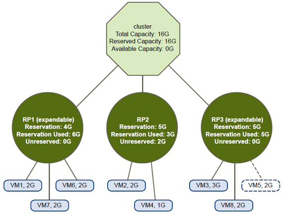
A valid cluster can be configured as follows:
- A cluster with total resources of 16GHz.
- RP1 and RP3 are of type Expandable, RP2 is of type Fixed.
- The total reservation used of the three resource pools combined is 16GHz (6GHz for RP1, 5GHz for RP2, and 5GHz for RP3). 16GHz shows up as the Reserved Capacity for the cluster at top level.
- RP1 was created with a reservation of 4GHz. Three virtual machines of 2GHz each are powered on. Two of those virtual machines (for example, VM1 and VM7) can use RP1’s reservations, the third virtual machine (VM6) can use reservations from the cluster’s resource pool. (If the type of this resource pool were Fixed, you could not power on the additional virtual machine.)
- RP2 was created with a reservation of 5GHz. Two virtual machines of 1GHz and 2GHz are powered on (Reservation Used: 3GHz). 2GHz remains unreserved.
RP3 was created with a reservation of 5GHz. Two virtual machines of 3GHz and 2GHz are powered on. Even though this resource pool is of type Expandable, no additional 2GHz virtual machine can be powered on because the parent’s extra resources are already used by RP1.
Overcommitted DRS Clusters
A cluster becomes overcommitted (yellow) when the tree of resource pools and virtual machines is internally consistent but the cluster does not have the capacity to support all resources reserved by the child resource pools.
There will always be enough resources to support all running virtual machines because, when a host becomes unavailable, all its virtual machines become unavailable. A cluster typically turns yellow when cluster capacity is suddenly reduced, for example, when a host in the cluster becomes unavailable. VMware recommends that you leave adequate additional cluster resources to avoid your cluster turning yellow.
Yellow Cluster
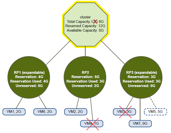
In this example:
- A cluster with total resources of 12GHz coming from three hosts of 4GHz each.
- Three resource pools reserving a total of 12GHz.
- The total reservation used by the three resource pools combined is 12GHz (4+5+3 GHz). That shows up as the Reserved Capacity in the cluster.
- One of the 4GHz hosts becomes unavailable, so total resources reduce to 8GHz.
- At the same time, VM4 (1GHz) and VM3 (3GHz), which were running on the host that failed, are no longer running.
- The cluster is now running virtual machines that require a total of 6GHz. The cluster still has 8GHz available, which is sufficient to meet virtual machine requirements.
The resource pool reservations of 12GHz can no longer be met, so the cluster is marked as yellow.
Invalid DRS Clusters
A cluster enabled for DRS becomes invalid (red) when the tree is no longer internally consistent, that is, resource constraints are not observed.
The total amount of resources in the cluster does not affect whether the cluster is red. A cluster can be red, even if enough resources exist at the root level, if there is an inconsistency at a child level.
You can resolve a red DRS cluster problem either by powering off one or more virtual machines, moving virtual machines to parts of the tree that have sufficient resources, or editing the resource pool settings in the red part.
Adding resources typically helps only when you are in the yellow state.
A cluster can also turn red if you reconfigure a resource pool while a virtual machine is failing over. A virtual machine that is failing over is disconnected and does not count toward the reservation used by the parent resource pool. You might reduce the reservation of the parent resource pool before the failover completes.
After the failover is complete, the virtual machine resources are again charged to the parent resource pool. If the pool’s usage becomes larger than the new reservation, the cluster turns red.
If a user is able to start a virtual machine (in an unsupported way) with a reservation of 3GHz under resource pool 2, the cluster would become red, as shown in the following figure.
Red Cluster

Properly apply virtual machine automation levels based upon application requirements
Official Documentation:
vSphere Resource Management Guide, Chapter 10, “Creating a DRS Cluster”, Section “Set a Custom Automation Level for a Virtual Machine”, Page 57.
After you create a DRS cluster, you can customize the automation level for individual virtual machines to override the cluster’s default automation level.
For example, you can select Manual for specific virtual machines in a cluster with full automation, or Partially Automated for specific virtual machines in a manual cluster.
If a virtual machine is set to Disabled, vCenter Server does not migrate that virtual machine or provide migration recommendations for it. This is known as pinning the virtual machine to its registered host.
NOTE If you have not enabled Enhanced vMotion Compatibility (EVC) for the cluster, fault tolerant virtual machines are set to DRS disabled. They appear on this screen, but you cannot assign an automation mode to them.
Procedure
- In the vSphere Client, right-click the cluster in the inventory and select Edit Settings.
- In the left pane under vSphere DRS, select Virtual Machine Options.
- Select the Enable individual virtual machine automation levels check box.
- (Optional) To temporarily disable any individual virtual machine overrides, deselect the Enable individual virtual machine automation levels check box.
Virtual machine settings are restored when the check box is selected again.
- (Optional) To temporarily suspend all vMotion activity in a cluster, put the cluster in manual mode and deselect the Enable individual virtual machine automation levels check box.
- Select one or more virtual machines.
- Click the Automation Level column and select an automation level from the drop-down menu.
| Option | Description |
| Manual | Placement and migration recommendations are displayed, but do not rununtil you manually apply the recommendation. |
| Fully Automated | Placement and migration recommendations run automatically. |
| Partially Automated | Initial placement is performed automatically. Migration recommendationsare displayed, but do not run. |
| Disabled | vCenter Server does not migrate the virtual machine or provide migrationrecommendations for it. |
- Click OK.
NOTE Other VMware products or features, such as vSphere vApp and vSphere Fault Tolerance, might override the automation levels of virtual machines in a DRS cluster. Refer to the product-specific documentation for details.
Create and administer ESXi host and Datastore Clusters
Official Documentation:
ESXi host Clusters
vSphere Resource Management Guide, Chapter 9, “Creating a DRS Cluster”, Page 51.
Datastore Clusters
vSphere Resource Management Guide, Chapter 10, “Creating a Datastore Cluster”, Page 77.
Creating a DRS Cluster
A DRS cluster is a collection of ESXi hosts and associated virtual machines with shared resources and a shared management interface. Before you can obtain the benefits of cluster-level resource management you must create a DRS cluster.
When you add a host to a DRS cluster, the host’s resources become part of the cluster’s resources. In addition to this aggregation of resources, with a DRS cluster you can support cluster-wide resource pools and enforce cluster-level resource allocation policies. The following cluster-level resource management capabilities are also available.
| Load Balancing | The distribution and usage of CPU and memory resources for all hosts andvirtual machines in the cluster are continuously monitored. DRS comparesthese metrics to an ideal resource utilization given the attributes of the cluster’sresource pools and virtual machines, the current demand, and the imbalance
target. It then performs (or recommends) virtual machine migrations accordingly. See “Virtual Machine Migration,” on page 53. When you first power on a virtual machine in the cluster, DRS attempts to maintain proper load balancing by either placing the virtual machine on an appropriate host or making a recommendation. See “Admission Control and Initial Placement,” on page 52. |
| Power management | When the vSphere Distributed Power Management (DPM) feature is enabled,DRS compares cluster- and host-level capacity to the demands of the cluster’svirtual machines, including recent historical demand. It places (or recommendsplacing) hosts in standby power mode if sufficient excess capacity is found or
powering on hosts if capacity is needed. Depending on the resulting host power state recommendations, virtual machines might need to be migrated to and from the hosts as well. See “Managing Power Resources,” on page 67. |
| Affinity Rules | You can control the placement of virtual machines on hosts within a cluster, byassigning affinity rules. See “Using DRS Affinity Rules,” on page 71. |
Depending on whether or not Enhanced vMotion Compatibility (EVC) is enabled, DRS behaves differently when you use vSphere Fault Tolerance (vSphere FT) virtual machines in your cluster.
| EVC | DRS (Load Balancing) | DRS (Initial Placement) |
| Enabled | Enabled (Primary and Secondary VMs) | Enabled (Primary and Secondary VMs) |
| Disabled | Disabled (Primary and Secondary VMs) | Disabled (Primary VMs)Fully Automated (Secondary VMs) |
Admission Control and Initial Placement
When you attempt to power on a single virtual machine or a group of virtual machines in a DRS-enabled cluster, vCenter Server performs admission control. It checks that there are enough resources in the cluster to support the virtual machine(s).
If the cluster does not have sufficient resources to power on a single virtual machine, or any of the virtual machines in a group power-on attempt, a message appears. Otherwise, for each virtual machine, DRS generates a recommendation of a host on which to run the virtual machine and takes one of the following actions
- Automatically executes the placement recommendation.
- Displays the placement recommendation, which the user can then choose to accept or override.
NOTE No initial placement recommendations are given for virtual machines on standalone hosts or in non-DRS clusters. When powered on, they are placed on the host where they currently reside.
Single Virtual Machine Power On
In a DRS cluster, you can power on a single virtual machine and receive initial placement recommendations.
When you power on a single virtual machine, you have two types of initial placement recommendations:
- A single virtual machine is being powered on and no prerequisite steps are needed.
The user is presented with a list of mutually exclusive initial placement recommendations for the virtual machine. You can select only one.
- A single virtual machine is being powered on, but prerequisite actions are required.
These actions include powering on a host in standby mode or the migration of other virtual machines from one host to another. In this case, the recommendations provided have multiple lines, showing each of the prerequisite actions. The user can either accept this entire recommendation or cancel powering on the virtual machine.
Group Power On
You can attempt to power on multiple virtual machines at the same time (group power on).
Virtual machines selected for a group power-on attempt do not have to be in the same DRS cluster. They can be selected across clusters but must be within the same datacenter. It is also possible to include virtual machines located in non-DRS clusters or on standalone hosts. These are powered on automatically and not included in any initial placement recommendation.
The initial placement recommendations for group power-on attempts are provided on a per-cluster basis. If all of the placement-related actions for a group power-on attempt are in automatic mode, the virtual machines are powered on with no initial placement recommendation given. If placement-related actions for any of the virtual machines are in manual mode, the powering on of all of the virtual machines (including those that are in automatic mode) is manual and is included in an initial placement recommendation.
For each DRS cluster that the virtual machines being powered on belong to, there is a single recommendation, which contains all of the prerequisites (or no recommendation). All such cluster-specific recommendations are presented together under the Power On Recommendations tab.
When a nonautomatic group power-on attempt is made, and virtual machines not subject to an initial placement recommendation (that is, those on standalone hosts or in non-DRS clusters) are included, vCenter Server attempts to power them on automatically. If these power ons are successful, they are listed under the Started Power-Ons tab. Any virtual machines that fail to power on are listed under the Failed Power-Ons tab.
Virtual Machine Migration
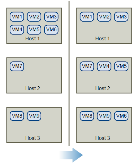
Although DRS performs initial placements so that load is balanced across the cluster, changes in virtual machine load and resource availability can cause the cluster to become unbalanced. To correct such imbalances, DRS generates migration recommendations.
If DRS is enabled on the cluster, load can be distributed more uniformly to reduce the degree of this imbalance.
For example, the three hosts on the left side of the following figure are unbalanced. Assume that Host 1, Host 2, and Host 3 have identical capacity, and all virtual machines have the same configuration and load (which includes reservation, if set). However, because Host 1 has six virtual machines, its resources might be overused while ample resources are available on Host 2 and Host 3. DRS migrates (or recommends the migration of) virtual machines from Host 1 to Host 2 and Host 3. On the right side of the diagram, the properly load balanced configuration of the hosts that results appears.
When a cluster becomes unbalanced, DRS makes recommendations or migrates virtual machines, depending on the default automation level:
- If the cluster or any of the virtual machines involved are manual or partially automated, vCenter Server does not take automatic actions to balance resources. Instead, the Summary page indicates that migration recommendations are available and the DRS Recommendations page displays recommendations for changes that make the most efficient use of resources across the cluster.
- If the cluster and virtual machines involved are all fully automated, vCenter Server migrates running virtual machines between hosts as needed to ensure efficient use of cluster resources.
NOTE Even in an automatic migration setup, users can explicitly migrate individual virtual machines, but vCenter Server might move those virtual machines to other hosts to optimize cluster resources.
By default, automation level is specified for the whole cluster. You can also specify a custom automation level for individual virtual machines.
DRS Migration Threshold
The DRS migration threshold allows you to specify which recommendations are generated and then applied (when the virtual machines involved in the recommendation are in fully automated mode) or shown (if in manual mode). This threshold is also a measure of how much cluster imbalance across host (CPU and memory) loads is acceptable.
You can move the threshold slider to use one of five settings, ranging from Conservative to Aggressive. The five migration settings generate recommendations based on their assigned priority level. Each setting you move the slider to the right allows the inclusion of one more lower level of priority. The Conservative setting generates only priority-one recommendations (mandatory recommendations), the next level to the right generates priority-two recommendations and higher, and so on, down to the Aggressive level which generates priority-five recommendations and higher (that is, all recommendations.)
A priority level for each migration recommendation is computed using the load imbalance metric of the cluster. This metric is displayed as Current host load standard deviation in the cluster’s Summary tab in the vSphere Client. A higher load imbalance leads to higher-priority migration recommendations. For more information about this metric and how a recommendation priority level is calculated, see the VMware Knowledge Base article “Calculating the priority level of a VMware DRS migration recommendation.”
After a recommendation receives a priority level, this level is compared to the migration threshold you set. If the priority level is less than or equal to the threshold setting, the recommendation is either applied (if the relevant virtual machines are in fully automated mode) or displayed to the user for confirmation (if in manual or partially automated mode.)
Migration Recommendations
If you create a cluster with a default manual or partially automated mode, vCenter Server displays migration recommendations on the DRS Recommendations page.
The system supplies as many recommendations as necessary to enforce rules and balance the resources of the cluster. Each recommendation includes the virtual machine to be moved, current (source) host and destination host, and a reason for the recommendation. The reason can be one of the following:
- Balance average CPU loads or reservations.
- Balance average memory loads or reservations.
- Satisfy resource pool reservations.
- Satisfy an affinity rule.
- Host is entering maintenance mode or standby mode.
NOTE If you are using the vSphere Distributed Power Management (DPM) feature, in addition to migration recommendations, DRS provides host power state recommendations.
Creating a Datastore Cluster
A datastore cluster is a collection of datastores with shared resources and a shared management interface.
Datastore clusters are to datastores what clusters are to hosts. When you create a datastore cluster, you can use vSphere Storage DRS to manage storage resources.
NOTE Datastore clusters are referred to as storage pods in the vSphere API.
When you add a datastore to a datastore cluster, the datastore’s resources become part of the datastore cluster’s resources. As with clusters of hosts, you use datastore clusters to aggregate storage resources, which enables you to support resource allocation policies at the datastore cluster level. The following resource management capabilities are also available per datastore cluster.
| Space utilization loadBalancing | You can set a threshold for space use. When space use on a datastore exceedsthe threshold, Storage DRS generates recommendations or performs StoragevMotion migrations to balance space use across the datastore cluster. |
| I/O latency loadBalancing | You can set an I/O latency threshold for bottleneck avoidance. When I/O latencyon a datastore exceeds the threshold, Storage DRS generates recommendationsor performs Storage vMotion migrations to help alleviate high I/O load. |
| Anti-affinity rules | You can create anti-affinity rules for virtual machine disks. For example, thevirtual disks of a certain virtual machine must be kept on different datastores.By default, all virtual disks for a virtual machine are placed on the samedatastore. |
Initial Placement and Ongoing Balancing
Storage DRS provides initial placement and ongoing balancing recommendations to datastores in a Storage DRS-enabled datastore cluster.
Initial placement occurs when Storage DRS selects a datastore within a datastore cluster on which to place a virtual machine disk. This happens when the virtual machine is being created or cloned, when a virtual machine disk is being migrated to another datastore cluster, or when you add a disk to an existing virtual machine.
Initial placement recommendations are made in accordance with space constraints and with respect to the goals of space and I/O load balancing. These goals aim to minimize the risk of over-provisioning one datastore, storage I/O bottlenecks, and performance impact on virtual machines.
Storage DRS is invoked at the configured frequency (by default, every eight hours) or when one or more datastores in a datastore cluster exceeds the user-configurable space utilization thresholds. When Storage DRS is invoked, it checks each datastore’s space utilization and I/O latency values against the threshold. For I/O latency, Storage DRS uses the 90th percentile I/O latency measured over the course of a day to compare against the threshold.
Storage Migration Recommendations
vCenter Server displays migration recommendations on the Storage DRS Recommendations page for datastore clusters that have manual automation mode.
The system provides as many recommendations as necessary to enforce Storage DRS rules and to balance the space and I/O resources of the datastore cluster. Each recommendation includes the virtual machine name, the virtual disk name, the name of the datastore cluster, the source datastore, the destination datastore, and a reason for the recommendation.
- Balance datastore space use
- Balance datastore I/O load
Storage DRS makes mandatory recommendations for migration in the following situations:
- The datastore is out of space.
- Anti-affinity or affinity rules are being violated.
- The datastore is entering maintenance mode and must be evacuated.
In addition, optional recommendations are made when a datastore is close to running out of space or when adjustments should be made for space and I/O load balancing.
Storage DRS considers moving virtual machines that are powered off or powered on for space balancing.
Storage DRS includes powered-off virtual machines with snapshots in these considerations.
Create a Datastore Cluster
You can manage datastore cluster resources using Storage DRS.
Procedure
- In the Datastores and Datastore Clusters view of the vSphere Client inventory, right-click the Datacenter object and select New Datastore Cluster.
- Follow the prompts to complete the Create Datastore Cluster wizard.
Enable and Disable Storage DRS
Storage DRS allows you to manage the aggregated resources of a datastore cluster. When Storage DRS is enabled, it provides recommendations for virtual machine disk placement and migration to balance space and I/O resources across the datastores in the datastore cluster.
When you enable Storage DRS, you enable the following functions.
- Space load balancing among datastores within a datastore cluster.
- I/O load balancing among datastores within a datastore cluster.
- Initial placement for virtual disks based on space and I/O workload.
The Enable Storage DRS check box in the Datastore Cluster Settings dialog box enables or disables all of these components at once. If necessary, you can disable I/O-related functions of Storage DRS independently of space balancing functions.
When you disable Storage DRS on a datastore cluster, Storage DRS settings are preserved. When you enable Storage DRS, the settings for the datastore cluster are restored to the point where Storage DRS was disabled.
Procedure
- In the vSphere Client inventory, right-click a datastore cluster and select Edit Settings.
- Click General.
- Select Turn on Storage DRS and click OK.
-
(Optional) To disable only I/O-related functions of Storage DRS, leaving space-related controls enabled, perform the following steps.
- Select SDRS Runtime Rules.
- Deselect the Enable I/O metric for Storage DRS check box.
- Select SDRS Runtime Rules.
- Click OK.
Set the Automation Level for Datastore Clusters
The automation level for a datastore cluster specifies whether or not placement and migration recommendations from Storage DRS are applied automatically.
Procedure
- In the vSphere Client inventory, right-click a datastore cluster and select Edit Settings.
- Select SDRS Automation.
- Select an automation level.
Manual is the default automation level.
| Option | Description |
| No Automation (Manual Mode) | Placement and migration recommendations are displayed, but do not rununtil you manually apply the recommendation. |
| Fully Automated | Placement and migration recommendations run automatically. |
- Click OK.
Setting the Aggressiveness Level for Storage DRS
The aggressiveness of Storage DRS is determined by specifying thresholds for space used and I/O latency.
Storage DRS collects resource usage information for the datastores in a datastore cluster. vCenter Server uses this information to generate recommendations for placement of virtual disks on datastores.
When you set a low aggressiveness level for a datastore cluster, Storage DRS recommends Storage vMotion migrations only when absolutely necessary, for example, if when I/O load, space utilization, or their imbalance is high. When you set a high aggressiveness level for a datastore cluster, Storage DRS recommends migrations whenever the datastore cluster can benefit from space or I/O load balancing.
In the vSphere Client, you can use the following thresholds to set the aggressiveness level for Storage DRS:
| Space Utilization | Storage DRS generates recommendations or performs migrations when thepercentage of space utilization on the datastore is greater than the thresholdyou set in the vSphere Client. |
| I/O Latency | Storage DRS generates recommendations or performs migrations when the90th percentile I/O latency measured over a day for the datastore is greater thanthe threshold. |
You can also set advanced options to further configure the aggressiveness level of Storage DRS.
| Space utilizationDifference | This threshold ensures that there is some minimum difference between thespace utilization of the source and the destination. For example, if the spaceused on datastore A is 82% and datastore B is 79%, the difference is 3. If thethreshold is 5, Storage DRS will not make migration recommendations from
datastore A to datastore B. |
| I/O load balancinginvocation interval | After this interval, Storage DRS runs to balance I/O load. |
| I/O imbalance threshold | Lowering this value makes I/O load balancing less aggressive. Storage DRScomputes an I/O fairness metric between 0 and 1, which 1 being the fairestdistribution. I/O load balancing runs only if the computed metric is less than 1- (I/O imbalance threshold / 100). |
Set Storage DRS Runtime Rules
Set Storage DRS triggers and configure advanced options for the datastore cluster.
Procedure
-
(Optional) Select or deselect the Enable I/O metric for SDRS recommendations check box to enable or disable I/O metric inclusion.
When you disable this option, vCenter Server does not consider I/O metrics when making Storage DRS recommendations. When you disable this option, you disable the following elements of Storage DRS:
- I/O load balancing among datastores within a datastore cluster.
- Initial placement for virtual disks based on I/O workload. Initial placement is based on space only.
- I/O load balancing among datastores within a datastore cluster.
-
(Optional) Set Storage DRS thresholds.
You set the aggressiveness level of Storage DRS by specifying thresholds for used space and I/O latency.
- Use the Utilized Space slider to indicate the maximum percentage of consumed space allowed before Storage DRS is triggered. Storage DRS makes recommendations and performs migrations when space use on the datastores is higher than the threshold.
- Use the I/O Latency slider to indicate the maximum I/O latency allowed before Storage DRS is triggered. Storage DRS makes recommendations and performs migrations when latency is higher than the threshold.
NOTE The Storage DRS I/O Latency threshold for the datastore cluster should be lower than or equal to the Storage I/O Control congestion threshold.
- Use the Utilized Space slider to indicate the maximum percentage of consumed space allowed before Storage DRS is triggered. Storage DRS makes recommendations and performs migrations when space use on the datastores is higher than the threshold.
-
(Optional) Configure advanced options.
- No recommendations until utilization difference between source and destination is: Use the slider to specify the space utilization difference threshold. Utilization is usage * 100/capacity.
This threshold ensures that there is some minimum difference between the space utilization of the source and the destination. For example, if the space used on datastore A is 82% and datastore B is 79%, the difference is 3. If the threshold is 5, Storage DRS will not make migration recommendations from datastore A to datastore B.
- Evaluate I/O load every: Specify how often Storage DRS should assess space and I/O load balancing.
- I/O imbalance threshold: Use the slider to indicate the aggressiveness of I/O load balancing. Lowering this value makes I/O load balancing less aggressive. Storage DRS computes an I/O fairness metric between 0 and 1, which 1 being the fairest distribution. I/O load balancing runs only if the computed metric is less than 1 – (I/O imbalance threshold / 100).
- No recommendations until utilization difference between source and destination is: Use the slider to specify the space utilization difference threshold. Utilization is usage * 100/capacity.
- Click Next.
Datastore Cluster Requirements
Datastores and hosts that are associated with a datastore cluster must meet certain requirements to use datastore cluster features successfully.
Follow these guidelines when you create a datastore cluster.
-
Datastore clusters must contain similar or interchangeable datastores.
A datastore cluster can contain a mix of datastores with different sizes and I/O capacities, and can be from different arrays and vendors. However, the following types of datastores cannot coexist in a datastore cluster.
- NFS and VMFS datastores cannot be combined in the same datastore cluster.
- Replicated datastores cannot be combined with non-replicated datastores in the same Storage-DRSenabled datastore cluster.
- NFS and VMFS datastores cannot be combined in the same datastore cluster.
- All hosts attached to the datastores in a datastore cluster must be ESXi 5.0 and later. If datastores in the datastore cluster are connected to ESX/ESXi 4.x and earlier hosts, Storage DRS does not run.
- Datastores shared across multiple datacenters cannot be included in a datastore cluster.
- As a best practice, do not include datastores that have hardware acceleration enabled in the same datastore cluster as datastores that do not have hardware acceleration enabled. Datastores in a datastore cluster must be homogeneous to guarantee hardware acceleration-supported behavior.
Adding and Removing Datastores from a Datastore Cluster
You add and remove datastores to and from an existing datastore cluster by dragging them in the vSphere Client inventory.
You can add to a datastore cluster any datastore that is mounted on a host in the vSphere Client inventory, with the following exceptions:
- All hosts attached to the datastore must be ESXi 5.0 and later.
- The datastore cannot be in more than one datacenter in the same instance of the vSphere Client.
When you remove a datastore from a datastore cluster, the datastore remains in the vSphere Client inventory and is not unmounted from the host.
Administer DRS / Storage DRS
Official Documentation:
vSphere Resource Management Guide, Chapter 10, “Using DRS Clusters to Manage Resources”, Page 59.
Datastore Clusters
vSphere Resource Management Guide, Chapter 12, “Using Datastore Clusters to Manage Storage Resources”, Page 83.
See previous objective.
Other exam notes
- The Saffageek VCAP5-DCA Objectives http://thesaffageek.co.uk/vcap5-dca-objectives/
- Paul Grevink The VCAP5-DCA diaries http://paulgrevink.wordpress.com/the-vcap5-dca-diaries/
- Edward Grigson VCAP5-DCA notes http://www.vexperienced.co.uk/vcap5-dca/
- Jason Langer VCAP5-DCA notes http://www.virtuallanger.com/vcap-dca-5/
- The Foglite VCAP5-DCA notes http://thefoglite.com/vcap-dca5-objective/
VMware vSphere official documentation
| VMware vSphere Basics Guide | html | epub | mobi | |
| vSphere Installation and Setup Guide | html | epub | mobi | |
| vSphere Upgrade Guide | html | epub | mobi | |
| vCenter Server and Host Management Guide | html | epub | mobi | |
| vSphere Virtual Machine Administration Guide | html | epub | mobi | |
| vSphere Host Profiles Guide | html | epub | mobi | |
| vSphere Networking Guide | html | epub | mobi | |
| vSphere Storage Guide | html | epub | mobi | |
| vSphere Security Guide | html | epub | mobi | |
| vSphere Resource Management Guide | html | epub | mobi | |
| vSphere Availability Guide | html | epub | mobi | |
| vSphere Monitoring and Performance Guide | html | epub | mobi | |
| vSphere Troubleshooting | html | epub | mobi | |
| VMware vSphere Examples and Scenarios Guide | html | epub | mobi |
Disclaimer.
The information in this article is provided “AS IS” with no warranties, and confers no rights. This article does not represent the thoughts, intentions, plans or strategies of my employer. It is solely my opinion.