Knowledge
- Identify common virtual switch configurations
Skills and Abilities
- Configure SNMP
- Determine use cases for and applying VMware DirectPath I/O
- Migrate a vSS network to a Hybrid or Full vDS solution
- Configure vSS and vDS settings using command line tools
- Analyze command line output to identify vSS and vDS configuration details
- Configure NetFlow
-
Determine appropriate discovery protocol
- CDP
- LLDP
Configure SNMP
Official Documentation:
vSphere Monitoring and Performance, Chapter 8 “Monitoring Networked Devices with SNMP and vSphere”, page 63
Simple Network Management Protocol (SNMP) allows management programs to monitor and control a variety of networked devices.
Managed systems run SNMP agents, which can provide information to a management program in at least one of the following ways:
- In response to a GET operation, which is a specific request for information from the management system.
- By sending a trap, which is an alert sent by the SNMP agent to notify the management system of a particular event or condition.
Optionally, you can configure ESXi hosts to convert CIM indications to SNMP traps, allowing this information to be received by SNMP monitoring systems.
Management Information Base (MIB) files define the information that can be provided by managed devices.
The MIB files contain object identifiers (OIDs) and variables arranged in a hierarchy.
vCenter Server and ESXi have SNMP agents. The agent provided with each product has differing capabilities.
Using SNMP Traps with vCenter Server
The SNMP agent included with vCenter Server can be used to send traps when the vCenter Server system is started and when an alarm is triggered on vCenter Server. The vCenter Server SNMP agent functions only as
a trap emitter and does not support other SNMP operations, such as GET.
The traps sent by vCenter Server are typically sent to other management programs. You must configure your management server to interpret the SNMP traps sent by vCenter Server.
To use the vCenter Server SNMP traps, configure the SNMP settings on vCenter Server and configure your management client software to accept the traps from vCenter Server.
The traps sent by vCenter Server are defined in VMWARE-VC-EVENT-MIB.mib. See “VMWARE-VC-EVENTMIB,” on page 78.
Determine use cases for and applying VMware DirectPath I/O
Official Documentation:
vSphere Virtual Machine Administration, Chapter 8, Section “Add a PCI Device in the vSphere Client”, page 149.
vSphere Networking, Chapter 5, Section “DirectPath I/O”, page 43
vSphere DirectPath I/O allows a guest operating system on a virtual machine to directly access physical PCI and PCIe devices connected to a host. Each virtual machine can be connected to up to six PCI devices. PCI devices connected to a host can be marked as available for passthrough from the Hardware Advanced Settings in the Configuration tab for the host.
Snapshots are not supported with PCI vSphere Direct Path I/O devices.
Prerequisites
- To use DirectPath I/O, verify that the host has Intel® Virtualization Technology for Directed I/O (VT-d) or AMD I/O Virtualization Technology (IOMMU) enabled in the BIOS.
- Verify that the PCI devices are connected to the host and marked as available for passthrough.
- Verify that the virtual machine is using hardware version 7 or later.
Procedure
- In the vSphere Client inventory, right-click the virtual machine and select Edit Settings.
- On the Hardware tab, click Add.
- In the Add Hardware wizard, select PCI Device and click Next.
- Select the passthrough device to connect to the virtual machine from the drop-down list and click Next.
- Click Finish.
More information
- VMware document Configuration Examples and Troubleshooting for VMDirectPath
- VMware KB article 1010789 Configuring VMDirectPath I/O pass-through devices on an ESX host.
- Petri IT Knowledgebase http://www.petri.co.il/vmware-esxi4-vmdirectpath.htm
Migrate a vSS network to a Hybrid or Full vDS solution
Official Documentation:
vSphere Networking, Chapter 2 and Chapter 3 contain a lot of information on setting up vSphere Standard Switches and vSphere Distributed Switches, but no specific information on this objective.
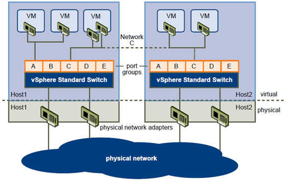
vSphere Standard Switches
You can create abstracted network devices called vSphere standard switches. A standard switch can route traffic internally between virtual machines and link to external networks.
You can use standard switches to combine the bandwidth of multiple network adapters and balance communications traffic among them. You can also configure a standard switch to handle physical NIC failover.
A vSphere standard switch models a physical Ethernet switch. The default number of logical ports for a standard switch is 120. You can connect one network adapter of a virtual machine to each port. Each uplink
adapter associated with a standard switch uses one port. Each logical port on the standard switch is a member of a single port group. Each standard switch can also have one or more port groups assigned to it. For
information about maximum allowed ports and port groups, see the Configuration Maximums documentation.
When two or more virtual machines are connected to the same standard switch, network traffic between them is routed locally. If an uplink adapter is attached to the standard switch, each virtual machine can access the
external network that the adapter is connected to.
Standard Port Groups
Port groups aggregate multiple ports under a common configuration and provide a stable anchor point for virtual machines connecting to labeled networks.
Each port group is identified by a network label, which is unique to the current host. Network labels are used to make virtual machine configuration portable across hosts. All port groups in a datacenter that are physically
connected to the same network (in the sense that each can receive broadcasts from the others) are given the same label. Conversely, if two port groups cannot receive broadcasts from each other, they have distinct labels.
A VLAN ID, which restricts port group traffic to a logical Ethernet segment within the physical network, is optional. For a port group to reach port groups located on other VLANs, the VLAN ID must be set to 4095. If you use VLAN IDs, you must change the port group labels and VLAN IDs together so that the labels properly represent connectivity.
Port Group Configuration for Virtual Machines
You can add or modify a virtual machine port group from the vSphere Client.
The vSphere Client Add Network wizard guides you through the tasks to create a virtual network to which virtual machines can connect, including creating a vSphere standard switch and configuring settings for a network label.
When you set up virtual machine networks, consider whether you want to migrate the virtual machines in the network between hosts. If so, be sure that both hosts are in the same broadcast domain—that is, the same Layer
2 subnet.
ESXidoes not support virtual machine migration between hosts in different broadcast domains because the migrated virtual machine might require systems and resources that it would no longer have access to in the new network. Even if your network configuration is set up as a high-availability environment or includes intelligent switches that can resolve the virtual machine’s needs across different networks, you might experience lag times as the Address Resolution Protocol (ARP) table updates and resumes network traffic for the virtual machines.
Virtual machines reach physical networks through uplink adapters. A vSphere standard switch can transfer data to external networks only when one or more network adapters are attached to it. When two or more adapters are attached to a single standard switch, they are transparently teamed.
VMkernel Networking Configuration
A VMkernel networking interface provides network connectivity for the host as well as handling Vmware vMotion, IP storage, and Fault Tolerance.
Moving a virtual machine from one host to another is called migration. Using vMotion, you can migrate powered on virtual machines with no downtime. Your VMkernel networking stack must be set up properly to accommodate vMotion.
IP storage refers to any form of storage that uses TCP/IP network ESXi. Because these storage types are network based, they can use the same VMkernel interface and port group.
TCP/IP Stack at the VMkernel Level
The VMware VMkernel TCP/IP networking stack provides networking support in multiple ways for each of the services it handles.
The VMkernel TCP/IP stack handles iSCSI, NFS, and vMotion in the following ways.
- iSCSI as a virtual machine datastore.
- iSCSI for the direct mounting of .ISO files, which are presented as CD-ROMs to virtual machines.
- NFS as a virtual machine datastore.
- NFS for the direct mounting of .ISO files, which are presented as CD-ROMs to virtual machines.
- Migration with vMotion.
- Fault Tolerance logging.
- Port-binding for vMotion interfaces.
- Provides networking information to dependent hardware iSCSI adapters.
If you have two or more physical NICs for iSCSI, you can create multiple paths for the software iSCSI by configuring iSCSI Multipathing. For more information about iSCSI Multipathing, see the vSphere Storage documentation.
vSphere Distributed Switch Architecture
A vSphere distributed switch functions as a single switch across all associated hosts. This enables you to set network configurations that span across all member hosts, and allows virtual machines to maintain consistent
network configuration as they migrate across multiple hosts.
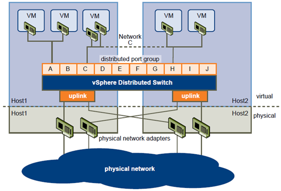
Like a vSphere standard switch, each vSphere distributed switch is a network hub that virtual machines can use. A distributed switch can forward traffic internally between virtual machines or link to an external network by connecting to physical Ethernet adapters, also known as uplink adapters.
Each distributed switch can also have one or more distributed port groups assigned to it. Distributed port groups group multiple ports under a common configuration and provide a stable anchor point for virtual machines connecting to labeled networks. Each distributed port group is identified by a network label, which is unique to the current datacenter. A VLAN ID, which restricts port group traffic to a logical Ethernet segment within the physical network, is optional.
Network resource pools allow you to manage network traffic by type of network traffic.
In addition to vSphere distributed switches, vSphere 5 also provides support for third-party virtual switches. For information about configuring the Cisco Nexus 1000v switch, go to http://www.cisco.com/go/1000vdocs.
Configuring a vSphere Distributed Switch
You can create a vSphere distributed switch on a vCenter Server datacenter. After you have created a vSphere distributed switch, you can add hosts, create distributed port groups, and edit distributed switch properties and policies.
Add a vSphere Distributed Switch
Create a vSphere distributed switch on a vCenter Server datacenter to handle networking traffic for all associated hosts on the datacenter.
If your system has complex port group requirements, create a distributed port group rather than a default port group.
Procedure
- In the vSphere Client, select the Networking inventory view and select the datacenter.
- Select Inventory > Datacenter > New vSphere Distributed Switch.
- Select a vSphere distributed switch version.
| Option | Description |
| vSphere Distributed Switch Version:4.0 | Compatible with ESX/ESXi version 4.0 and later. Features released with latervSphere distributed switch versions are not supported. |
| vSphere Distributed Switch Version:4.1.0 | Compatible with ESX/ESXi version 4.1 and later. Features released with latervSphere distributed switch versions are not supported. |
| vSphere Distributed Switch Version:5.0.0 | Compatible with ESXi version 5.0 and later. |
- Click Next.
- In the Name text box, type a name for the new vSphere distributed switch.
- Use the arrow buttons to select the Number of uplink ports, and click Next. Uplink ports connect the distributed switch to physical NICs on associated hosts. The number of uplink ports is the maximum number of allowed physical connections to the distributed switch per host.
- Select whether to add hosts and their physical adapters to the vSphere distributed switch now or later.
If you select Add now, select the hosts and physical adapters to use by clicking the check box next to each host or adapter. You can only free physical adapters to a vSphere distributed switch during distributed switch creation. -
(Optional) Set the maximum number of ports on a host.
- Click View Details for the host.
- Select the maximum number of ports for the host from the drop-down menu.
- Click OK.
- Click Next.
- (Optional) Select whether to Automatically create a default port group.
This option creates a distributed port group with default settings. - Click Finish.
Migrate an Existing Virtual Adapter to a vSphere Distributed Switch
You can migrate an existing virtual adapter from a vSphere standard switch to a vSphere distributed switch.
Procedure
- Log in to the vSphere Client and select the Hosts and Clusters inventory view.
- Select the host in the inventory pane.
- On the host Configuration tab, click Networking.
- Select the vSphere Distributed Switch view.
- Click Manage Virtual Adapters.
- Click Add.
- Select Migrate existing virtual network adapters and click Next.
- Select one or more virtual network adapters to migrate.
- For each selected adapter, choose a port group from the Select a port group drop-down menu.
- Click Next.
- Click Finish.
Migrate a Virtual Adapter to a vSphere Standard Switch
You can migrate an existing virtual adapter from a vSphere distributed switch to a vSphere standard switch.
Procedure
- Log in to the vSphere Client and select the Hosts and Clusters inventory view.
- Select the host in the inventory pane.
- On the host Configuration tab, click Networking.
- Select the vSphere Distributed Switch view.
- Click Manage Virtual Adapters.
- Select the virtual adapter to migrate, and click Migrate.
- Select the standard switch to migrate the adapter to and click Next.
- Enter a Network Label and optionally a VLAN ID for the virtual adapter, and click Next.
- Click Finish to migrate the virtual adapter and complete the wizard.
Migrate Virtual Machines to Or from a vSphere Distributed Switch
In addition to connecting virtual machines to a distributed switch at the individual virtual machine level, you can migrate a group of virtual machines between a vSphere distributed switch network and a vSphere standard
switch network.
Procedure
- Log in to the vSphere Client and select the Networking inventory view.
- Right-click the datacenter and selectMigrate Virtual Machine Networking.
The Migrate Virtual Machine Networking wizard appears. - Select a Source Network to migrate adapters from.
| Option | Description |
| Include all virtual machine network |
adapters that are connected to the
following network (Filter by Network)Migrates virtual machine network adapters from a particular network. Select
the source network from the Network drop-down menu.Include all virtual machine network
adapters that are connected to the
following network (Filter by VDS)Migrates virtual machine network adapters from a network on a particular
vSphere distributed switch. To migrate from a network, select Switch and
Network from the drop-down menus.Include all virtual machine network
adapters that are not connected to
any networkMigrates virtual machine network adapters that are not connected to any
network.
- Select a Destination Network to migrate adapters to.
| Option | Description |
| Filter by Network | Migrates virtual machine network adapters to a particular network. Select |
the destination network from the Network drop-down menu.Filter by VDSMigrates virtual machine network adapters to a network on a particular
vSphere Distritubed Switch. To migrate to a network, select Switch and
Network from the drop-down menus.
- Click Next.
- (Optional) Highlight a virtual machine or adapter to view their details.
- Select the virtual machines and adapters to migrate to the destination network and click Next.
- Verify that the source network, destination network, and number of virtual machines to migrate are correct and click OK.
More information
- http://www.vmware.com/files/pdf/vsphere-vnetwork-ds-migration-configuration-wp.pdf
- http://www.yellow-bricks.com/2011/04/21/distributed-vswitches-go-hybrid-or-go-distributed/
Configure vSS and vDS settings using command line tools
Official Documentation:
vSphere Command-Line Interface Concepts and Examples, Chapter 9 “Managing vSphere Networking”, page 109.
Vmware PowerCLI Documentation
VMware offers two completely different CLI’s with options to configure and analyze output of vSS and vDS.
- The VMware vSphere CLI, available on a ESXi host, as an installable package on a Windows or Linux Client or as part of the VMware Management Assistant (vMA)
- The VMware vSphere PowerCLI, available on any client that supports Microsoft’s Powershell
With Vmware vSphere CLI
Retrieving Basic Networking Information
Service console commands for retrieving networking information are not included in the ESXi Shell. You can instead use ESXCLI commands directly in the shell or use vCLI commands.
On ESXi 5.0, ifconfig information should be the information of the VMkernel NIC that attaches to the Management Network port group. You can retrieve information by using ESXCLI commands.
esxcli <conn_options> network ip interface list
esxcli <conn_options> network ip interface ipv4 get -n vmk<X>
esxcli <conn_options> network ip interface ipv6 get -n vmk<X>
esxcli <conn_options> network ip interface ipv6 address list
For information corresponding to the Linux netstat command, use the following ESXCLI command.
esxcli <conn_options> network ip connection list
Setting Up vSphere Networking with vSphere Standard Switches
You can set up your virtual network by performing these tasks.
- Create or manipulate virtual switches using esxcli network vswitch or vicfg-vswitch. By default, each ESXi host has one virtual switch, vSwitch0. You can create additional virtual switches or manage existing switches. See “Setting Up Virtual Switches and Associating a Switch with a Network Interface” on page 112.
- (Optional) Make changes to the uplink adapter using esxcli network vswitch standard uplink or vicfg-nics. See “Managing Uplink Adapters” on page 117.
- (Optional) Use esxcli network vswitch standard portgroup or vicfg-vswitch to add port groups to the virtual switch. See “Managing Port Groups with vicfg‐vswitch” on page 115.
- (Optional) Use esxcli network vswitch standard portgroup set or vicfg-vswitch to establish VLANs by associating port groups with VLAN IDs. See “Setting the Port Group VLAN ID with vicfg‐vswitch” on page 116.
- Use esxcli network ip interface or vicfg-vmknic to configure the VMkernel network interfaces. See “Adding and Modifying VMkernel Network Interfaces” on page 119.
Retrieving Information About Virtual Switches
You can retrieve information about virtual switches by using ESXCLI or vicfg-vswitch. Specify one of the options listed in “Connection Options” on page 17 in place of <conn_options>.
Retrieving Information about Virtual Switches with ESXCLI
You can retrieve information about virtual switches by using esxcli network vswitch commands.
- List all virtual switches and associated port groups.
esxcli <conn_options> network vswitch standard list
The command prints information about the virtual switch, which might include its name, number of ports, MTU, port groups, and other information. The output includes information about CDP settings for the virtual switch. The precise information depends on the target system. The default port groups are Management Network and VM Network.
- List the network policy settings (security policy, traffic shaping policy, and failover policy) for the virtual switch. The following commands are supported.
esxcli <conn_options> network vswitch standard policy failover get
esxcli <conn_options> network vswitch standard policy security get
esxcli <conn_options> network vswitch standard policy shaping get
Retrieving Information about Virtual Switches with vicfg-vswitch
You can retrieve information about virtual switches by using the vcifg-vswitch command. Specify one of the options listed in “Connection Options” on page 17 in place of <conn_options>.
- Check whether vSwitch1 exists.
vicfg-vswitch <conn_options> -c vSwitch1
- List all virtual switches and associated port groups.
vicfg-vswitch <conn_options> -l
The command prints information about the virtual switch, which might include its name, number of ports, MTU, port groups, and other information. The default port groups are Management Network and VM Network. - Retrieve the current CDP (Cisco Discovery Protocol) setting for this virtual switch.
If CDP is enabled on a virtual switch, ESXi administrators can find out which Cisco switch port is connected to which virtual switch uplink. CDP is a link‐level protocol that supports discovery of CDP‐aware network hardware at either end of a direct connection. CDP is bit forwarded through switches. CDP is a simple advertisement protocol which beacons information about the switch or host and some port information.
vicfg-vswitch <conn_options> –get-cdp vSwitch1
Adding and Deleting Virtual Switches
You can add and delete virtual switches with ESXCLI and with vicfg-vswitch.
Adding and Deleting Virtual Switches with ESXCLI
You can add and delete virtual switches using the esxcli network vswitch standard namespace. Specify one of the options listed in “Connection Options” on page 17 in place of <conn_options>.
- Add a virtual switch.
esxcli <conn_options> network vswitch standard add –vswitch-name=vSwitch42
You can specify the number of port groups while adding the virtual switch. If you do not specify a value, the default value is used. The system‐wide port count cannot be greater than 4096.
esxcli <conn_options> network vswitch standard add –vswitch-name=vSwitch42 –ports=8
After you have added a virtual switch, you can set switch attributes (“Setting Switch Attributes with esxcli network vswitch standard” on page 114) and add one or more uplink adapters (“Linking and Unlinking Uplink Adapters with ESXCLI” on page 119).
- Delete a virtual switch.
esxcli <conn_options> network vswitch standard remove –vswitch-name=vSwitch42
You cannot delete a virtual switch if any ports on the switch are still in use by VMkernel networks or virtual machines. Run esxcli network vswitch standard list to determine whether a virtual switch is in use.
Adding and Deleting Virtual Switches with vicfg-vswitch
You can add and delete virtual switches using the –add|-a and –delete|-d options. Specify one of the options listed in “Connection Options” on page 17 in place of <conn_options>.
- Add a virtual switch.
vicfg-vswitch <conn_options> –add vSwitch2
After you have added a virtual switch, you can set switch attributes (“Setting Switch Attributes with vicfg‐vswitch” on page 114) and add one or more uplink adapters (“Linking and Unlinking Uplink Adapters with vicfg‐vswitch” on page 119).
- Delete a virtual switch.
vicfg-vswitch <conn_options> –delete vSwitch1
You cannot delete a virtual switch if any ports on the switch are still in use by VMkernel networks, virtual machines, or vswifs. Run vicfg-vswitch –list to determine whether a virtual switch is in use.
Checking, Adding, and Removing Port Groups
You can check, add, and remove port groups with ESXCLI and with vicfg-vswitch.
Managing Port Groups with ESXCLI
Network services connect to vSwitches through port groups. A port group allows you to group traffic and specify configuration options such as bandwidth limitations and VLAN tagging policies for each port in the port group. A virtual switch must have one port group assigned to it. You can assign additional port groups.
You can use esxcli network vswitch standard portgroup to check, add, and remove port groups. Specify one of the options listed in “Connection Options” on page 17 in place of <conn_options>.
- List port groups currently associated with a virtual switch.
esxcli <conn_options> network vswitch standard portgroup list
Lists the port group name, associated virtual switch, active clients, and VLAN ID.
- Add a port group.
esxcli <conn_options> network vswitch standard portgroup add –portgroup-name=<name> –vswitch-name=vSwitch1 - Delete one of the existing port groups.
esxcli <conn_options> network vswitch standard portgroup remove –portgroup-name=<name> –vswitch-name=vSwitch1
Managing Port Groups with vicfg-vswitch
Network services connect to virtual switches through port groups. A port group allows you to group traffic and specify configuration options such as bandwidth limitations and VLAN tagging policies for each port in the port group. A virtual switch must have one port group assigned to it. You can assign additional port groups. Specify one of the options listed in “Connection Options” on page 17 in place of <conn_options>.
You can use vicfg-vswitch to check, add, and remove port groups.
- Check whether port groups are currently associated with a virtual switch.
vicfg-vswitch <conn_options> –check-pg <port_group> vSwitch1
The command returns 0 if the specified port group is associated with the virtual switch, and returns 1 otherwise. Use vicfg-vswitch –list to list all port groups.
- Add a port group.
vicfg-vswitch <conn_options> –add-pg <port_group_name> vSwitch1 - Delete one of the existing port groups.
vicfg-vswitch <conn_options> –del-pg <port_group_name> vSwitch1
Managing Uplinks and Port Groups
You can manage uplinks and port groups with ESXCLI and with vicfg-vswitch.
Connecting and Disconnecting Uplink Adapters and Port Groups with ESXCLI
If your setup includes one or more port groups, you can associate each port group with one or more uplink adapters (and remove the association). This functionality allows you to filter traffic from a port group to a specific uplink, even if the virtual switch is connected with multiple uplinks. Specify one of the options listed in “Connection Options” on page 17 in place of <conn_options>.
- Connect a port group with an uplink adapter.
esxcli <conn_options> network vswitch standard portgroup policy failover set –active-uplinks=vmnic1,vmnic6,vmnic7
This command fails silently if the uplink adapter does not exist.
- Make some of the adapters standby instead of active.
esxcli <conn_options> network vswitch standard portgroup policy failover set –standby-uplinks=vmnic1,vmnic6,vmnic7
Connecting and Disconnecting Uplinks and Port Groups with vicfg-vswitch
If your setup includes one or more port groups, you can associate each port group with one or more uplink adapters (and remove the association). This functionality allows you to filter traffic from a port group to a specific uplink, even if the virtual switch is connected with multiple uplinks. Specify one of the options listed in “Connection Options” on page 17 in place of <conn_options>.
- Connect a port group with an uplink adapter.
vicfg-vswitch <conn_options> –add-pg-uplink <adapter_name> –pg <port_group> <vswitch_name>
This command fails silently if the uplink adapter does not exist.
- Remove a port group from an uplink adapter.
vicfg-vswitch <conn_options> –del-pg-uplink <adapter_name> –pg <port_group> <vswitch_name>
Setting the Port Group VLAN ID
You can set the port group VLAN ID with ESXCLI and with vicfg-vswitch.
Setting the Port Group VLAN ID with ESXCLI
VLANs allow you to further segment a single physical LAN segment so that groups of ports are isolated as if they were on physically different segments. The standard is IEEE 802.1Q.
A VLAN ID restricts port group traffic to a logical Ethernet segment within the physical network.
- Set the VLAN ID to 4095 to allow a port group to reach port groups located on other VLAN.
- Set the VLAN ID to 0 to disable the VLAN for this port group.
If you use VLAN IDs, you must change the port group labels and VLAN IDs together so that the labels properly represent connectivity. VLAN IDs are optional.
You can use the following commands for VLAN management:
- Allow port groups to reach port groups located on other VLANs.
esxcli <conn_options> network vswitch standard portgroup set -p <pg_name> –vlan-id 4095
Call the command multiple times to allow all ports to reach port groups located on other VLANs.
- Disable VLAN for port group g42
esxcli <conn_options> network vswitch standard portgroup set –vlan-id 0 -p <pg_name>
Setting the Port Group VLAN ID with vicfg-vswitch
VLANs allow you to further segment a single physical LAN segment so that groups of ports are isolated as if they were on physically different segments. The standard is IEEE 802.1Q.
A VLAN ID restricts port group traffic to a logical Ethernet segment within the physical network.
- Set the VLAN ID to 4095 to allow a port group to reach port groups located on other VLAN.
- Set the VLAN ID to 0 to disable the VLAN for this port group.
If you use VLAN IDs, you must change the port group labels and VLAN IDs together so that the labels properly represent connectivity. VLAN IDs are optional.
You can use the following commands for VLAN management:
- Allow all port groups to reach port groups located on other VLANs.
vicfg-vswitch <conn_options> –vlan 4095 –pg “ALL” vSwitch2
- Disable VLAN for port group g42.
vicfg-vswitch <conn_options> –vlan 0 –pg g42 vSwitch2
Run vicfg-vswitch -l to retrieve information about VLAN IDs currently associated with the virtual switches in the network.
Run esxcli network vswitch standard portgroup list to list all port groups and associated VLAN IDs.
Managing Uplink Adapters
You can manage uplink adapters, which represent the physical NICs that connect the ESXi host to the network by using the esxcli network nics or the vicfg-nics command. You can also use esxcli network vswitch and esxcfg-vswitch to link and unlink the uplink.
You can use vicfg-nics to list information and to specify speed and duplex setting for the uplink.
You can use esxcli network nic to list all uplinks, to list information, to set attributes, and to bring a specified uplink down or up.
Managing Uplink Adapters with esxcli network nic
The following example workflow lists all uplink adapters, lists properties for one uplink adapter, changes the uplink’s speed and duplex settings, and brings the uplink down and back up. Specify one of the options listed
in “Connection Options” on page 17 in place of <conn_options>.
Setting Up vSphere Networking with vSphere Distributed Switch
A distributed switch functions as a single virtual switch across all associated hosts. A distributed switch allows virtual machines to maintain a consistent network configuration as they migrate across multiple hosts. See
“Networking Using vSphere Distributed Switches” on page 111.
Like a vSphere standard switch, each distributed switch is a network hub that virtual machines can use. A distributed switch can forward traffic internally between virtual machines or link to an external network by connecting to uplink adapters.
Each distributed switch can have one or more distributed port groups assigned to it. Distributed port groups group multiple ports under a common configuration and provide a stable anchor point for virtual machines that are connecting to labeled networks. Each distributed port group is identified by a network label, which is unique to the current datacenter. A VLAN ID, which restricts port group traffic to a logical Ethernet segment within the physical network, is optional.
You can create distributed switches by using the vSphere Client. After you have created a distributed switch, you can add hosts by using the vSphere Client, create distributed port groups, and edit distributed switch properties and policies with the vSphere Client. You can add and remove uplink ports by using vicfg-vswitch.
IMPORTANT In vSphere 5.0, you cannot create distributed virtual switches with ESXCLI.
See the vSphere Networking documentation and the white paper available through the Resources link at http://www.vmware.com/go/networking for information about distributed switches and how to configure them using the vSphere Client.
You can add and remove distributed switch uplink ports with vicfg-vswitch.
IMPORTANT You cannot add and remove uplink ports with ESXCLI.
After the distributed switch has been set up, you can use vicfg-vswitch to add or remove uplink ports.
Specify one of the options listed in “Connection Options” on page 17 in place of <conn_options>.
- Add an uplink port.
vicfg-vswitch <conn_options> –add-dvp-uplink <adapter_name> –dvp <DVPort_id> <dvswitch_name>
- Remove an uplink port.
vicfg-vswitch <conn_options> –del-dvp-uplink <adapter> –dvp <DVPort_id> <dvswitch_name>
With Vmware PowerCLI
PowerCLI is an extension to PowerShell. You may download PowerCLI 5.0.1 from VMware for free (Login Required). A generic list of networking PowerCLI commands can be located in the following fashion:
- Run PowerCLI as an Administrator
- Execute: Get-Command *net* -CommandType Cmdlet (You may replace *net* with *nic* to find additional network related commands)
- To acquire help on any command, execute: Get-Help Command
| Command | Description |
| Get-ExternalNetwork | Retrieves cloud external networks. You can filter the returned networks by name, Id, virtual Lan Id, and provider Vdc. Note: This cmdlet is only available to Provider Administrators. |
| Get-NetworkAdapter | Retrieves the virtual network adapters available on a vSphere server. The cmdlet returns a set of virtual network adapters assigned to the virtual machines, templates, and snapshots specified by the VirtualMachine, Template, and Snapshot parameters. At least one of these parameters must be provided. To specify a server different from the default one, use the -Server parameter. |
| Get-OrgNetwork | Retrieves cloud organization networks. You can filter the output by using the cmdlet parameters. |
| Get-VMGuestNetworkInterface | Retrieves information about the network configuration of the specified virtual machines or guests. This cmdlet supports only Windows XP 32 SP3, Windows Server 2003 32bit SP2, Windows Server 2003 64bit SP2, Windows 7 64 bit, Windows Server 2008 R2 64bit and Redhat Enterprise 5 operating systems. |
| Get-VMHostNetwork | Retrieves the host networks on a vSphere server. This command retrieves the networking configuration of the hosts specified by the VMHost parameter. To specify a server different from the default one, use the -Server parameter. |
| Get-VMHostNetworkAdapter | Retrieves the host network adapters on a vSphere server. |
| New-VMHostNetworkAdapter | Creates a new HostVirtualNIC (Service Console or VMKernel) on the specified host. Creates a port group with a name specified by the PortGroup parameter on the virtual switch passed through the VirtualSwitch parameter. Adds either a Console NIC if ConsoleNIC is set, or a VMKernel NIC otherwise. |
| Remove-NetworkAdapter | Removes the virtual network adapters from their locations. |
| Remove-VMHostNetworkAdapter | Removes the virtual network adapters from their locations. |
| Set-NetworkAdapter | Changes the configuration of the virtual network adapter. You can change the MAC address and the network name, and to configure the Connected, StartConnected, and WakeOnLan properties of the adapter. |
| Set-VMGuestNetworkInterface | Configures the network settings of a virtual machine using VMware Tools. The cmdlet allows IP and routing configuration. You can modify Wins settings only for Windows virtual machines. The cmdlet sends a remote script which executes inside the virtual machine in the context of the specified user account. This cmdlet supports only Windows XP 32 SP3, Windows Server 2003 32bit SP2, Windows Server 2003 64bit SP2, Windows 7 64 bit, Windows Server 2008 R2 64bit and Redhat Enterprise 5 operating systems. |
| Set-VMHostNetwork | Updates the specified virtual network. The service console and the VMkernel are often not connected to the same network, and therefore each needs its own gateway information. A gateway is needed for connectivity to machines not on the same IP subnet as the service console or VMkernel. |
| Set-VMHostNetworkAdapter | Configures the specified host network adapter. For a physical NIC, you can change the duplex and the bit rate settings (10, 100, 1000, 10000). For a regular virtual NIC, you can change the IP address and the subnet mask. For a console virtual NIC, you can modify the IP and the subnet mask, or choose DHCP mode. |
| Get-NicTeamingPolicy | Retrieves the Nic teaming policies of the specified virtual switches and virtual port groups. Nic teaming policy allows to determine how network traffic is distributed between adapters and how to reorganize traffic in case of adapter failure. |
| Get-OSCustomizationNicMapping | Retrieves the configured Nic setting mappings for the specified OS customization specification. |
| New-OSCustomizationNicMapping | Adds Nic settings mappings to the specified OS customization specifications. If the given specification is server-side, it is updated on the server. If it is client-side, the reference that is kept in-memory is updated but the variable that is passed to the cmdlet is not modified. |
| Remove-OSCustomizationNicMapping | Removes the specified OS customization NIC mappings. |
| Set-NicTeamingPolicy | Configures the specified NIC teaming policy. You can change the load balancing and failover settings. Default NIC teaming policies are set for the entire virtual switch and can be overridden at port group level. |
| Set-OSCustomizationNicMapping | Modifies the provided OS customization NIC mappings. If the parent spec of the provided NIC mapping is a server-side spec, it is updated on the server. If the parent spec is client-side, the reference that is kept in the memory is updated, but the variable that is passed to the cmdlet is not modified. |
Analyze command line output to identify vSS and vDS configuration details
Official Documentation:
See previous objective
Configure NetFlow
Official Documentation:
vSphere Networking, Chapter 6 “Advanced Networking”, section “Configure NetFlow”, page 72.
Vmware vSphere Blog, vSphere 5 New Networking Features – NetFlow
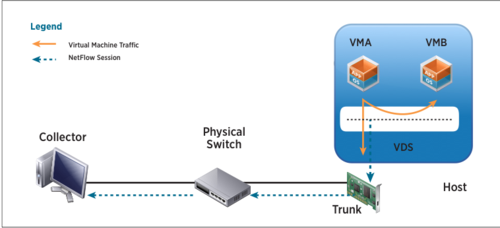
NetFlow is a networking protocol that collects IP traffic information as records and sends them to a collector such as CA NetQoS for traffic flow analysis. VMware vSphere 5 supports NetFlow v5, which is the most common version supported by network devices. NetFlow capability in the vSphere 5 platform provides visibility into virtual infrastructure traffic that includes:
- Intrahost virtual machine traffic (virtual machine–to–virtual machine traffic on the same host)
- Interhost virtual machine traffic (virtual machine–to–virtual machine traffic on different hosts)
- Virtual machine to physical infrastructure traffic
Figure below shows a Distributed Switch configured to send NetFlow records to a collector that is connected to an external physical network switch. The blue dotted line with arrow indicates the NetFlow session that is established to send flow records for the collector to analyze.
Usage
NetFlow capability on a Distributed Switch along with a NetFlow collector tool helps monitor application flows and measures flow performance over time. It also helps in capacity planning and ensuring that I/O resources are utilized properly by different applications, based on their needs.
IT administrators who want to monitor the performance of application flows running in the virtualized environment can enable flow monitoring on a Distributed Switch.
Configuration
NetFlow on Distributed Switches can be enabled at the port group level, at an individual port level or at the uplink level. When configuring NetFlow at the port level, administrators should select the NetFlow override tab, which will make sure that flows are monitored even if the port group–level NetFlow is disabled.
The NetFlow configuration screen below shows the different parameters that can be controlled during the setup.
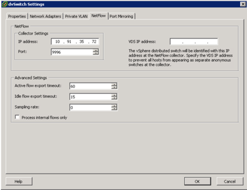
- The Collector Settings of IP address and Port should be configured according to the information collected about the collector tool installed in your environment.
- The Advanced Settings parameters allow you to control the timeout and sampling rate for the flows. To change the amount of information that is collected for a flow, you can change the sampling rate. For example, a sampling rate of 2 indicates that the VDS will collect data from every other packet. You can also modify the Idle flow export timeout values.
- The VDS IP address configuration is useful when you want to see all flow information in the collector tool as part of one VDS IP address and not as a separate host management network IP address. In this example screen shot, because the VDS IP address is not entered, the collector tool will provide flow details under each host’s management network IP address.
You can also monitor only internal flows of the virtual infrastructure by checking “Process Internal flows only” box.
I almost always get the question about the CPU impact of enabling NetFlow feature. Just wanted to address that while I am on this topic. Answer is, it all depends on how many flows you have in your environment and what traffic rate they are operating at. If you think you have lot many flows in your environment and are concerned about CPU resources, you can use the controls provided in the NetFlow setup to choose which flows gets monitored. For example, you can change the sampling rate or choose to monitor only internal flows. Also, you can selectively enable or disable NetFlow on a port group or a port.
As customers move to virtualize Tier 1 applications, they need the proper tools to manage the SLA requirements of these applications. NetFlow feature on vSphere 5 platform helps in monitoring these tier 1 application flows and also helps in capacity planning of network resources.
Configure NetFlow Settings
NetFlow is a network analysis tool that you can use to monitor network monitoring and virtual machine traffic.
NetFlow is available on vSphere distributed switch version 5.0.0 and later.
Procedure
- Log in to the vSphere Client and select the Networking inventory view.
- Right-click the vSphere distributed switch in the inventory pane, and select Edit Settings.
- Navigate to the NetFlow tab.
- Type the IP address and Port of the NetFlow collector.
- Type the VDS IP address.
With an IP address to the vSphere distributed switch, the NetFlow collector can interact with the vSphere distributed switch as a single switch, rather than interacting with a separate, unrelated switch for each associated host. - (Optional) Use the up and down menu arrows to set the Active flow export timeout and Idle flow export timeout.
- (Optional) Use the up and down menu arrows to set the Sampling rate.
The sampling rate determines what portion of data NetFlow collects, with the sampling rate number determining how often NetFlow collects the packets. A collector with a sampling rate of 2 collects data from every other packet. A collector with a sampling rate of 5 collects data from every fifth packet. - (Optional) Select Process internal flows only to collect data only on network activity between virtual machines on the same host.
- Click OK.
More information
Determine appropriate discovery protocol
Official Documentation:
vSphere Networking, Chapter 6 “Advanced Networking”, section “Switch Discovery Protocol”, page 72.
Switch Discovery Protocol
Switch discovery protocols allow vSphere administrators to determine which switch port is connected to a given vSphere standard switch or vSphere distributed switch.
vSphere 5.0 supports Cisco Discovery Protocol (CDP) and Link Layer Discovery Protocol (LLDP). CDP is available for vSphere standard switches and vSphere distributed switches connected to Cisco physical switches. LLDP is available for vSphere distributed switches version 5.0.0 and later.
When CDP or LLDP is enabled for a particular vSphere distributed switch or vSphere standard switch, you can view properties of the peer physical switch such as device ID, software version, and timeout from the vSphere Client.
Enable Cisco Discovery Protocol on a vSphere Distributed Switch
Cisco Discovery Protocol (CDP) allows vSphere administrators to determine which Cisco switch port connects to a given vSphere standard switch or vSphere distributed switch. When CDP is enabled for a particular vSphere distributed switch, you can view properties of the Cisco switch (such as device ID, software version, and timeout) from the vSphere Client.
Procedure
- Log in to the vSphere Client and select the Networking inventory view.
- Right-click the vSphere distributed switch in the inventory pane, and select Edit Settings.
- On the Properties tab, select Advanced.
- Select Enabled from the Status drop-down menu.
- Select Cisco Discovery Protocol from the Type drop-down menu.
- Select the CDP mode from the Operation drop-down menu.
| Option | Description |
| Listen | ESXi detects and displays information about the associated Cisco switch port, |
but information about the vSphere distributed switch is not available to the
Cisco switch administrator.AdvertiseESXi makes information about the vSphere distributed switch available to
the Cisco switch administrator, but does not detect and display information
about the Cisco switch.BothESXi detects and displays information about the associated Cisco switch and
makes information about the vSphere distributed switch available to the
Cisco switch administrator.
- Click OK.
Enable Link Layer Discovery Protocol on a vSphere Distributed Switch
With Link Layer Discovery Protocol (LLDP), vSphere administrators can determine which physical switch port connects to a given vSphere distributed switch. When LLDP is enabled for a particular distributed switch, you can view properties of the physical switch (such as chassis ID, system name and description, and device capabilities) from the vSphere Client.
LLDP is available only on vSphere distributed switch version 5.0.0 and later.
Procedure
- Log in to the vSphere Client and select the Networking inventory view.
- Right-click the vSphere distributed switch in the inventory pane, and select Edit Settings.
- On the Properties tab, select Advanced.
- Select Enabled from the Status drop-down menu.
- Select Link Layer Discovery Protocol from the Type drop-down menu.
- Select the LLDP mode from the Operation drop-down menu.
| Option | Description |
| Listen | ESXi detects and displays information about the associated physical switch |
port, but information about the vSphere distributed switch is not available
to the switch administrator.AdvertiseESXi makes information about the vSphere distributed switch available to
the switch administrator, but does not detect and display information about
the physical switch.BothESXi detects and displays information about the associated physical switch
and makes information about the vSphere distributed switch available to the
switch administrator.
- Click OK.
View Switch Information on the vSphere Client
When CDP or LLDP is set to Listen or Both, you can view physical switch information from the vSphere Client.
Procedure
- Log in to the vSphere Client and select the host from the inventory panel.
- Click the Configuration tab and click Networking.
- Click the information icon to the right of the vSphere standard switch or vSphere distributed switch to display information for that switch.
Switch information for the selected switch appears.
Other exam notes
- The Saffageek VCAP5-DCA Objectives http://thesaffageek.co.uk/vcap5-dca-objectives/
- Paul Grevink The VCAP5-DCA diaries http://paulgrevink.wordpress.com/the-vcap5-dca-diaries/
- Edward Grigson VCAP5-DCA notes http://www.vexperienced.co.uk/vcap5-dca/
- Jason Langer VCAP-DCA notes http://www.virtuallanger.com/vcap-dca-5/
- The Foglite VCAP5-DCA notes http://thefoglite.com/vcap-dca5-objective/
VMware vSphere official documentation
| VMware vSphere Basics Guide | html | epub | mobi | |
| vSphere Installation and Setup Guide | html | epub | mobi | |
| vSphere Upgrade Guide | html | epub | mobi | |
| vCenter Server and Host Management Guide | html | epub | mobi | |
| vSphere Virtual Machine Administration Guide | html | epub | mobi | |
| vSphere Host Profiles Guide | html | epub | mobi | |
| vSphere Networking Guide | html | epub | mobi | |
| vSphere Storage Guide | html | epub | mobi | |
| vSphere Security Guide | html | epub | mobi | |
| vSphere Resource Management Guide | html | epub | mobi | |
| vSphere Availability Guide | html | epub | mobi | |
| vSphere Monitoring and Performance Guide | html | epub | mobi | |
| vSphere Troubleshooting | html | epub | mobi | |
| VMware vSphere Examples and Scenarios Guide | html | epub | mobi |
Disclaimer.
The information in this article is provided “AS IS” with no warranties, and confers no rights. This article does not represent the thoughts, intentions, plans or strategies of my employer. It is solely my opinion.