Knowledge
- Explain the Pluggable Storage Architecture (PSA) layout
Skills and Abilities
- Install and Configure PSA plug-ins
- Understand different multipathing policy functionalities
- Perform command line configuration of multipathing options
- Change a multipath policy
-
Configure Software iSCSI port binding
Install and Configure PSA plug-ins
Official Documentation:
vSphere Storage Guide, Chapter 16, “VMkernel and Storage” , page 149. and vSphere Storage Guide, Chapter 17, “Managing Multiple Paths” , page 158
The VMkernel is a high-performance operating system that runs directly on the ESXi host. The Vmkernel manages most of the physical resources on the hardware, including memory, physical processors, storage, and networking controllers.
To manage storage, VMkernel has a storage subsystem that supports several Host Bus Adapters (HBAs) including parallel SCSI, SAS, Fibre Channel, FCoE, and iSCSI. These HBAs connect a wide variety of activeactive, active-passive, and ALUA storage arrays that are certified for use with the VMkernel. See the vSphere Compatibility Guide for a list of the supported HBAs and storage arrays.
The primary file system that the VMkernel uses is the VMware Virtual Machine File System (VMFS). VMFS is a cluster file system designed and optimized to support large files such as virtual disks and swap files. The VMkernel also supports the storage of virtual disks on NFS file systems.
The storage I/O path provides virtual machines with access to storage devices through device emulation. This device emulation allows a virtual machine to access files on a VMFS or NFS file system as if they were SCSI devices. The VMkernel provides storage virtualization functions such as the scheduling of I/O requests from multiple virtual machines and multipathing.
In addition, VMkernel offers several Storage APIs that enable storage partners to integrate and optimize their products for vSphere.
The following graphic illustrates the basics of the VMkernel core, with special attention to the storage stack.
Storage-related modules reside between the logical device I/O scheduler and the adapter I/O scheduler layers.

Storage APIs
Storage APIs is a family of APIs used by third-party hardware, software, and storage providers to develop components that enhance several vSphere features and solutions.
This publication describes the following sets of Storage APIs and explains how they contribute to your storage environment. For information about other APIs from this family, including Storage API – Data Protection and Storage API – Site Recovery Manager, see the VMware Web site.
- Storage APIs – Multipathing, also known as the Pluggable Storage Architecture (PSA). PSA is a collection of VMkernel APIs that allows storage partners to enable and certify their arrays asynchronous to ESXi release schedules, as well as deliver performance-enhancing, multipathing and load-balancing behaviors that are optimized for each array. For more information, see “Managing Multiple Paths,” on page 158.
-
Storage APIs – Array Integration, formerly known as VAAI, include the following APIs:
- Hardware Acceleration APIs. Allows arrays to integrate with vSphere to transparently offload certain storage operations to the array. This integration significantly reduces CPU overhead on the host. See Chapter 18, “Storage Hardware Acceleration,” on page 173.
- Array Thin Provisioning APIs. Help to monitor space use on thin-provisioned storage arrays to prevent out-of-space conditions, and to perform space reclamation. See “Array Thin Provisioning and VMFS Datastores,” on page 186.
- Storage APIs – Storage Awareness. These vCenter Server-based APIs enable storage arrays to inform the vCenter Server about their configurations, capabilities, and storage health and events. See Chapter 20, “Using Storage Vendor Providers,” on page 191.
Managing Multiple Paths
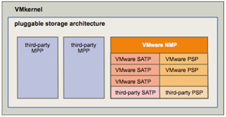
To manage storage multipathing, ESXi uses a collection of Storage APIs, also called the Pluggable Storage Architecture (PSA). The PSA is an open, modular framework that coordinates the simultaneous operation of multiple multipathing plug-ins (MPPs). The PSA allows 3rd party software developers to design their own load balancing techniques and failover mechanisms for particular storage array, and insert their code directly into the ESXi storage I/O path.
Topics discussing path management use the following acronyms.
| Acronym | Definition |
| PSA | Pluggable Storage Architecture |
| NMP | Native Multipathing Plug-In. Generic VMware multipathingmodule. |
| PSP | Path Selection Plug-In, also called Path Selection Policy.Handles path selection for a given device. |
| SATP | Storage Array Type Plug-In, also called Storage Array TypePolicy. Handles path failover for a given storage array. |
The VMkernel multipathing plug-in that ESXi provides by default is the VMware Native Multipathing Plug-In (NMP). The NMP is an extensible module that manages sub plug-ins. There are two types of NMP sub plugins, Storage Array Type Plug-Ins (SATPs), and Path Selection Plug-Ins (PSPs). SATPs and PSPs can be built-in and provided by VMware, or can be provided by a third party.
If more multipathing functionality is required, a third party can also provide an MPP to run in addition to, or as a replacement for, the default NMP.
When coordinating the VMware NMP and any installed third-party MPPs, the PSA performs the following tasks:
- Loads and unloads multipathing plug-ins.
- Hides virtual machine specifics from a particular plug-in.
- Routes I/O requests for a specific logical device to the MPP managing that device.
- Handles I/O queueing to the logical devices.
- Implements logical device bandwidth sharing between virtual machines.
- Handles I/O queueing to the physical storage HBAs.
- Handles physical path discovery and removal.
- Provides logical device and physical path I/O statistics.
As the Pluggable Storage Architecture illustration shows, multiple third-party MPPs can run in parallel with
the VMware NMP. When installed, the third-party MPPs replace the behavior of the NMP and take complete
control of the path failover and the load-balancing operations for specified storage devices.
The multipathing modules perform the following operations:
- Manage physical path claiming and unclaiming.
- Manage creation, registration, and deregistration of logical devices.
- Associate physical paths with logical devices.
- Support path failure detection and remediation.
-
Process I/O requests to logical devices:
- Select an optimal physical path for the request.
- Depending on a storage device, perform specific actions necessary to handle path failures and I/O command retries.
- Support management tasks, such as reset of logical devices.
Understand different multipathing policy functionalities
Official Documentation:
vSphere Storage Guide, Chapter 17, “Understanding Multipathing and Failover , page 153.
VMware Multipathing Module
By default, ESXi provides an extensible multipathing module called the Native Multipathing Plug-In (NMP).
Generally, the VMware NMP supports all storage arrays listed on the VMware storage HCL and provides a default path selection algorithm based on the array type. The NMP associates a set of physical paths with a specific storage device, or LUN. The specific details of handling path failover for a given storage array are delegated to a Storage Array Type Plug-In (SATP). The specific details for determining which physical path is used to issue an I/O request to a storage device are handled by a Path Selection Plug-In (PSP). SATPs and PSPs are sub plug-ins within the NMP module.
With ESXi, the appropriate SATP for an array you use will be installed automatically. You do not need to obtain
or download any SATPs.
VMware SATPs
Storage Array Type Plug-Ins (SATPs) run in conjunction with the VMware NMP and are responsible for arrayspecific operations.
ESXi offers a SATP for every type of array that VMware supports. It also provides default SATPs that support non-specific active-active and ALUA storage arrays, and the local SATP for direct-attached devices. Each SATP accommodates special characteristics of a certain class of storage arrays and can perform the array-specific operations required to detect path state and to activate an inactive path. As a result, the NMP module itself can work with multiple storage arrays without having to be aware of the storage device specifics.
After the NMP determines which SATP to use for a specific storage device and associates the SATP with the physical paths for that storage device, the SATP implements the tasks that include the following:
- Monitors the health of each physical path.
- Reports changes in the state of each physical path.
- Performs array-specific actions necessary for storage fail-over. For example, for active-passive devices, it can activate passive paths.
VMware PSPs
Path Selection Plug-Ins (PSPs) are sub plug-ins of the VMware NMP and are responsible for choosing a physical path for I/O requests.
The VMware NMP assigns a default PSP for each logical device based on the SATP associated with the physical paths for that device. You can override the default PSP. For information, see “Change the Path Selection Policy,” on page 163.
By default, the VMware NMP supports the following PSPs:
| VMW_PSP_MRU | The host selects the path that it used most recently. When the path becomesunavailable, the host selects an alternative path. The host does not revert backto the original path when that path becomes available again. There is nopreferred path setting with the MRU policy. MRU is the default policy for mostactive-passive storage devices.Displayed in the vSphere Client as the Most Recently Used (VMware) path
selection policy. |
| VMW_PSP_FIXED | The host uses the designated preferred path, if it has been configured.Otherwise, it selects the first working path discovered at system boot time. Ifyou want the host to use a particular preferred path, specify it manually. Fixedis the default policy for most active-active storage devices.NOTE If the host uses a default preferred path and the path’s status turns toDead, a new path is selected as preferred. However, if you explicitly designate
the preferred path, it will remain preferred even when it becomes inaccessible. Displayed in the vSphere Client as the Fixed (VMware) path selection policy. |
| VMW_PSP_RR | The host uses an automatic path selection algorithm rotating through all activepaths when connecting to active-passive arrays, or through all available pathswhen connecting to active-active arrays. RR is the default for a number of arraysand can be used with both active-active and active-passive arrays to implementload balancing across paths for different LUNs.Displayed in the vSphere Client as the Round Robin (VMware) path selection
policy. |
VMware NMP Flow of I/O
When a virtual machine issues an I/O request to a storage device managed by the NMP, the following process takes place.
- The NMP calls the PSP assigned to this storage device.
- The PSP selects an appropriate physical path on which to issue the I/O.
- The NMP issues the I/O request on the path selected by the PSP.
- If the I/O operation is successful, the NMP reports its completion.
- If the I/O operation reports an error, the NMP calls the appropriate SATP.
- The SATP interprets the I/O command errors and, when appropriate, activates the inactive paths.
- The PSP is called to select a new path on which to issue the I/O.
Path Scanning and Claiming
When you start your ESXi host or rescan your storage adapter, the host discovers all physical paths to storage devices available to the host. Based on a set of claim rules, the host determines which multipathing plug-in (MPP) should claim the paths to a particular device and become responsible for managing the multipathing support for the device.
By default, the host performs a periodic path evaluation every 5 minutes causing any unclaimed paths to be claimed by the appropriate MPP.
The claim rules are numbered. For each physical path, the host runs through the claim rules starting with the lowest number first. The attributes of the physical path are compared to the path specification in the claim rule.
If there is a match, the host assigns the MPP specified in the claim rule to manage the physical path. This continues until all physical paths are claimed by corresponding MPPs, either third-party multipathing plugins or the native multipathing plug-in (NMP).
For the paths managed by the NMP module, a second set of claim rules is applied. These rules determine which Storage Array Type Plug-In (SATP) should be used to manage the paths for a specific array type, and which Path Selection Plug-In (PSP) is to be used for each storage device.
Use the vSphere Client to view which SATP and PSP the host is using for a specific storage device and the status of all available paths for this storage device. If needed, you can change the default VMware PSP using the vSphere Client. To change the default SATP, you need to modify claim rules using the vSphere CLI.
You can find some information about modifying claim rules in “Managing Storage Paths and Multipathing Plug-Ins,” on page 164.
For more information about the commands available to manage PSA, see Getting Started with vSphere Command-Line Interfaces.
For a complete list of storage arrays and corresponding SATPs and PSPs, see the SAN Array Model Reference section of the vSphere Compatibility Guide.
Perform command line configuration of multipathing options
Official Documentation:
vSphere Storage Guide, Chapter 17, “Understanding Multipathing and Failover , page 164, presents an overview of the available commands.
List Multipathing Claim Rules for the Host
Use the esxcli command to list available multipathing claim rules.
Claim rules indicate which multipathing plug-in, the NMP or any third-party MPP, manages a given physical path. Each claim rule identifies a set of paths based on the following parameters:
- Vendor/model strings
- Transportation, such as SATA, IDE, Fibre Channel, and so on
- Adapter, target, or LUN location
- Device driver, for example, Mega-RAID
In the procedure, –server=server_name specifies the target server. The specified target server prompts you for a user name and password. Other connection options, such as a configuration file or session file, are supported. For a list of connection options, see Getting Started with vSphere Command-Line Interfaces.
Prerequisites
Install vCLI or deploy the vSphere Management Assistant (vMA) virtual machine. See Getting Started with vSphere Command-Line Interfaces. For troubleshooting , run esxcli commands in the ESXi Shell.
Procedure
- Run the esxcli –server=server_name storage core claimrule list –claimrule-class=MP command to list the multipathing claim rules.
Example: Sample Output of the esxcli storage core claimrule list Command
| Rule Class | Rule | Class | Type | Plugin | Matches |
| MP | 0 | Runtime | Transport | NMP | Transport=usb |
| MP | 1 | runtime | Transport | NMP | transport=sata |
| MP | 2 | Runtime | Transport | NMP | transport=ide |
| MP | 3 | Runtime | Transport | NMP | transport=block |
| MP | 4 | Runtime | Transport | NMP | transport=unknown |
| MP | 101 | Runtime | Vendor | MASK_PATH | vendor=DELL model=Universal Xport |
| MP | 101 | File | Vendor | MASK_PATH | vendor=DELL model=Universal Xport |
| MP | 200 | Runtime | Vendor | MPP_1 | vendor=NewVend model=* |
| MP | 200 | File | Vendor | MPP_1 | vendor=NewVend model=* |
| MP | 201 | Runtime | Location | MPP_2 | adapter=vmhba41 channel=* target=* lun=* |
| MP | 201 | File | Location | MPP_2 | adapter=vmhba41 channel=* target=* lun=* |
| MP | 202 | Runtime | Driver | MPP_3 | driver=megaraid |
| MP | 202 | File | Driver | MPP_3 | driver=megaraid |
| MP | 65535 | Runtime | Vendor | NMP | vendor=* model=* |
This example indicates the following:
- The NMP claims all paths connected to storage devices that use the USB, SATA, IDE, and Block SCSI transportation.
- You can use the MASK_PATH module to hide unused devices from your host. By default, the PSA claim rule 101 masks Dell array pseudo devices with a vendor string of DELL and a model string of Universal Xport.
- The MPP_1 module claims all paths connected to any model of the NewVend storage array.
- The MPP_3 module claims the paths to storage devices controlled by the Mega-RAID device driver.
- Any paths not described in the previous rules are claimed by NMP.
- The Rule Class column in the output describes the category of a claim rule. It can be MP (multipathing plug-in), Filter, or VAAI.
- The Class column shows which rules are defined and which are loaded. The file parameter in the Class column indicates that the rule is defined. The runtime parameter indicates that the rule has been loaded into your system. For a user-defined claim rule to be active, two lines with the same rule number should exist, one line for the rule with the file parameter and another line with runtime. Several low numbered rules, have only one line with the Class of runtime. These are system-defined claim rules that you cannot modify.
Display Multipathing Modules
Use the esxcli command to list all multipathing modules loaded into the system. Multipathing modules manage physical paths that connect your host with storage.
In the procedure, –server=server_name specifies the target server. The specified target server prompts you for a user name and password. Other connection options, such as a configuration file or session file, are supported. For a list of connection options, see Getting Started with vSphere Command-Line Interfaces.
Prerequisites
Install vCLI or deploy the vSphere Management Assistant (vMA) virtual machine. See Getting Started with vSphere Command-Line Interfaces. For troubleshooting , run esxcli commands in the ESXi Shell.
Procedure
- To list multipathing modules, run the following command:
esxcli –server=server_name storage core plugin list –plugin-class=MP
This command typically shows the NMP and, if loaded, the MASK_PATH module. If any third-party MPPs have been loaded, they are listed as well.
Display SATPs for the Host
Use the esxcli command to list VMware NMP SATPs loaded into the system. Display information about the SATPs.
In the procedure, –server=server_name specifies the target server. The specified target server prompts you for a user name and password. Other connection options, such as a configuration file or session file, are supported. For a list of connection options, see Getting Started with vSphere Command-Line Interfaces.
Prerequisites
Install vCLI or deploy the vSphere Management Assistant (vMA) virtual machine. See Getting Started with vSphere Command-Line Interfaces. For troubleshooting , run esxcli commands in the ESXi Shell.
Procedure
- To list VMware SATPs, run the following command:
esxcli –server=server_name storage nmp satp list
For each SATP, the output displays information that shows the type of storage array or system this SATP supports and the default PSP for any LUNs using this SATP. Placeholder (plugin not loaded) in the Description column indicates that the SATP is not loaded.
Display NMP Storage Devices
Use the esxcli command to list all storage devices controlled by the VMware NMP and display SATP and PSP information associated with each device.
In the procedure, –server=server_name specifies the target server. The specified target server prompts you for a user name and password. Other connection options, such as a configuration file or session file, are supported. For a list of connection options, see Getting Started with vSphere Command-Line Interfaces.
Prerequisites
Install vCLI or deploy the vSphere Management Assistant (vMA) virtual machine. See Getting Started with vSphere Command-Line Interfaces. For troubleshooting , run esxcli commands in the ESXi Shell.
Procedure
- To list all storage devices, run the following command:
esxcli –server=server_name storage nmp device list
Use the –device | -d=device_ID option to filter the output of this command to show a single device.
Add Multipathing Claim Rules
Use the esxcli commands to add a new multipathing PSA claim rule to the set of claim rules on the system.
For the new claim rule to be active, you first define the rule and then load it into your system.
You add a new PSA claim rule when, for example, you load a new multipathing plug-in (MPP) and need to define which paths this module should claim. You may need to create a claim rule if you add new paths and want an existing MPP to claim them.
CAUTION When creating new claim rules, be careful to avoid a situation where different physical paths to the same LUN are claimed by different MPPs. Unless one of the MPPs is the MASK_PATH MPP, this configuration will cause performance problems.
In the procedure, –server=server_name specifies the target server. The specified target server prompts you for a user name and password. Other connection options, such as a configuration file or session file, are supported. For a list of connection options, see Getting Started with vSphere Command-Line Interfaces.
Prerequisites
Install vCLI or deploy the vSphere Management Assistant (vMA) virtual machine. See Getting Started with vSphere Command-Line Interfaces. For troubleshooting , run esxcli commands in the ESXi Shell.
Procedure
- To define a new claim rule, run the following command:
esxcli –server=server_name storage core claimrule add
The command takes the following options:
| Option | Description |
| -A|–adapter=<str> | Indicate the adapter of the paths to use in this operation. |
| -u|–autoassign | The system will auto assign a rule ID. |
| -C|–channel=<long> | Indicate the channel of the paths to use in this operation. |
| -c|–claimrule-class=<str> | Indicate the claim rule class to use in this operation.Valid values are: MP, Filter, VAAI. |
| -d|–device=<str> | Indicate the device Uid to use for this operation. |
| -D|–driver=<str> | Indicate the driver of the paths to use in this operation. |
| -f|–force | Force claim rules to ignore validity checks and install the rule anyway. |
| –if-unset=<str> | Execute this command if this advanced user variable is not set to 1. |
| -i|–iqn=<str> | Indicate the iSCSI Qualified Name for the target to use in this operation. |
| -L|–lun=<long> | Indicate the LUN of the paths to use in this operation. |
| -M|–model=<str> | Indicate the model of the paths to use in this operation. |
| -P|–plugin=<str> | Indicate which PSA plugin to use for this operation. (required) |
| -r|–rule=<long> | Indicate the rule ID to use for this operation. |
| -T|–target=<long> | Indicate the target of the paths to use in this operation. |
| -R|–transport=<str> | Indicate the transport of the paths to use in this operation.Valid values are: block, fc, iscsi, iscsivendor, ide, sas, sata, usb, parallel,unknown. |
| -t|–type=<str> | Indicate which type of matching is used for claim/unclaim or claimrule.Valid values are: vendor, location, driver, transport, device, target. (required) |
| -V|–vendor=<str> | Indicate the vendor of the paths to user in this operation. |
| –wwnn=<str> | Indicate the World-Wide Node Number for the target to use in this operation. |
| –wwpn=<str> | Indicate the World-Wide Port Number for the target to use in this operation. |
- To load the new claim rule into your system, run the following command:
esxcli –server=server_name storage core claimrule load
This command loads all newly created multipathing claim rules from your system’s configuration file.
Delete Multipathing Claim Rules
Use the esxcli commands to remove a multipathing PSA claim rule from the set of claim rules on the system.
In the procedure, –server=server_name specifies the target server. The specified target server prompts you for a user name and password. Other connection options, such as a configuration file or session file, are supported. For a list of connection options, see Getting Started with vSphere Command-Line Interfaces.
Prerequisites
Install vCLI or deploy the vSphere Management Assistant (vMA) virtual machine. See Getting Started with vSphere Command-Line Interfaces. For troubleshooting , run esxcli commands in the ESXi Shell.
Procedure
- Delete a claim rule from the set of claim rules.
esxcli –server=server_name storage core claimrule remove
NOTE By default, the PSA claim rule 101 masks Dell array pseudo devices. Do not delete this rule, unless you want to unmask these devices.
The command takes the following options:
| Option | Description |
| -c|–claimrule-class=<str> | Indicate the claim rule class to use in this operation (MP, Filter, VAAI). |
| -P|–plugin=<str> | Indicate the plugin to use for this operation. |
| -r|–rule=<long> | Indicate the rule ID to use for this operation. |
This step removes the claim rule from the File class.
- Remove the claim rule from the system.
esxcli –server=server_name storage core claimrule load
This step removes the claim rule from the Runtime class.
Mask Paths
You can prevent the host from accessing storage devices or LUNs or from using individual paths to a LUN.
Use the esxcli commands to mask the paths. When you mask paths, you create claim rules that assign the MASK_PATH plug-in to the specified paths.
In the procedure, –server=server_name specifies the target server. The specified target server prompts you for a user name and password. Other connection options, such as a configuration file or session file, are supported. For a list of connection options, see Getting Started with vSphere Command-Line Interfaces.
Prerequisites
Install vCLI or deploy the vSphere Management Assistant (vMA) virtual machine. See Getting Started with vSphere Command-Line Interfaces. For troubleshooting , run esxcli commands in the ESXi Shell.
Procedure
- Check what the next available rule ID is.
esxcli –server=server_name storage core claimrule list
The claim rules that you use to mask paths should have rule IDs in the range of 101 – 200. If this command shows that rule 101 and 102 already exist, you can specify 103 for the rule to add. - Assign the MASK_PATH plug-in to a path by creating a new claim rule for the plug-in.
esxcli –server=server_name storage core claimrule add -P MASK_PATH - Load the MASK_PATH claim rule into your system.
esxcli –server=server_name storage core claimrule load - Verify that the MASK_PATH claim rule was added correctly.
esxcli –server=server_name storage core claimrule list - If a claim rule for the masked path exists, remove the rule.
esxcli –server=server_name storage core claiming unclaim - Run the path claiming rules.
esxcli –server=server_name storage core claimrule run
After you assign the MASK_PATH plug-in to a path, the path state becomes irrelevant and is no longer maintained by the host. As a result, commands that display the masked path’s information might show the path state as dead.
Unmask Paths
When you need the host to access the masked storage device, unmask the paths to the device.
In the procedure, –server=server_name specifies the target server. The specified target server prompts you for a user name and password. Other connection options, such as a configuration file or session file, are supported. For a list of connection options, see Getting Started with vSphere Command-Line Interfaces.
Prerequisites
Install vCLI or deploy the vSphere Management Assistant (vMA) virtual machine. See Getting Started with vSphere Command-Line Interfaces. For troubleshooting , run esxcli commands in the ESXi Shell.
Procedure
- Delete the MASK_PATH claim rule.
esxcli –server=server_name storage core claimrule remove -r rule# - Verify that the claim rule was deleted correctly.
esxcli –server=server_name storage core claimrule list - Reload the path claiming rules from the configuration file into the VMkernel.
esxcli –server=server_name storage core claimrule load - Run the esxcli –server=server_name storage core claiming unclaim command for each path to the
masked storage device.
For example:
esxcli –server=server_name storage core claiming unclaim -t location -A vmhba0 -C 0 -T 0 -L 149 - Run the path claiming rules.
esxcli –server=server_name storage core claimrule run
Your host can now access the previously masked storage device.
Define NMP SATP Rules
The NMP SATP claim rules specify which SATP should manage a particular storage device. Usually you do not need to modify the NMP SATP rules. If you need to do so, use the esxcli commands to add a rule to the list of claim rules for the specified SATP.
You might need to create a SATP rule when you install a third-party SATP for a specific storage array.
In the procedure, –server=server_name specifies the target server. The specified target server prompts you for a user name and password. Other connection options, such as a configuration file or session file, are supported. For a list of connection options, see Getting Started with vSphere Command-Line Interfaces.
Prerequisites
Install vCLI or deploy the vSphere Management Assistant (vMA) virtual machine. See Getting Started with vSphere Command-Line Interfaces. For troubleshooting , run esxcli commands in the ESXi Shell.
Procedure
- To add a claim rule for a specific SATP, run the
esxcli –server=server_name storage nmp satp rule add command. The command takes the following options.
| Option | Description |
| -b|–boot | This is a system default rule added at boot time. Do not modify esx.conf oradd to host profile. |
| -c|–claim-option=string | Set the claim option string when adding a SATP claim rule. |
| -e|–description=string | Set the claim rule description when adding a SATP claim rule. |
| -d|–device=string | Set the device when adding SATP claim rules. Device rules are mutuallyexclusive with vendor/model and driver rules. |
| -D|–driver=string | Set the driver string when adding a SATP claim rule. Driver rules aremutually exclusive with vendor/model rules. |
| -f|–force | Force claim rules to ignore validity checks and install the rule anyway. |
| -h|–help | Show the help message. |
| -M|–model=string | Set the model string when adding SATP a claim rule. Vendor/Model rulesare mutually exclusive with driver rules. |
| -o|–option=string | Set the option string when adding a SATP claim rule. |
| -P|–psp=string | Set the default PSP for the SATP claim rule. |
| -O|–psp-option=string | Set the PSP options for the SATP claim rule. |
| -s|–satp=string | The SATP for which a new rule will be added. |
| -R|–transport=string | Set the claim transport type string when adding a SATP claim rule. |
| -t|–type=string | Set the claim type when adding a SATP claim rule. |
| -V|–vendor=string | Set the vendor string when adding SATP claim rules. Vendor/Model rulesare mutually exclusive with driver rules. |
- Reboot your host.
Change a multipath policy
Official Documentation:
vSphere Storage Guide, Chapter 17, “Understanding Multipathing and Failover , page 163, describes how to change the Path selection Policy
Setting a Path Selection Policy
For each storage device, the ESXi host sets the path selection policy based on the claim rules.
By default, VMware supports the following path selection policies. If you have a third-party PSP installed on your host, its policy also appears on the list.
| Fixed (VMware) | The host uses the designated preferred path, if it has been configured.Otherwise, it selects the first working path discovered at system boot time. Ifyou want the host to use a particular preferred path, specify it manually. Fixedis the default policy for most active-active storage devices.NOTEIf the host uses a default preferred path and the path’s status turns toDead, a new path is selected as preferred. However, if you explicitly designate
the preferred path, it will remain preferred even when it becomes inaccessible. |
| Most Recently Used(VMware) | The host selects the path that it used most recently. When the path becomesunavailable, the host selects an alternative path. The host does not revert backto the original path when that path becomes available again. There is nopreferred path setting with the MRU policy. MRU is the default policy for mostactive-passive storage devices. |
| Round Robin (VMware) | The host uses an automatic path selection algorithm rotating through all activepaths when connecting to active-passive arrays, or through all available pathswhen connecting to active-active arrays. RR is the default for a number of arraysand can be used with both active-active and active-passive arrays to implementload balancing across paths for different LUNs. |
Change the Path Selection Policy
Generally, you do not have to change the default multipathing settings your host uses for a specific storage device. However, if you want to make any changes, you can use the Manage Paths dialog box to modify a path selection policy and specify the preferred path for the Fixed policy.
Procedure
- Open the Manage Paths dialog box either from the Datastores or Devices view.
-
Select a path selection policy.
By default, VMware supports the following path selection policies. If you have a third-party PSP installed on your host, its policy also appears on the list.- Fixed (VMware)
- Most Recently Used (VMware)
- Round Robin (VMware)
- For the fixed policy, specify the preferred path by right-clicking the path you want to assign as the preferred path, and selecting Preferred.
- Click OK to save your settings and exit the dialog box.
Disable Paths
You can temporarily disable paths for maintenance or other reasons. You can do so using the vSphere Client.
Procedure
- Open the Manage Paths dialog box either from the Datastores or Devices view.
- In the Paths panel, right-click the path to disable, and select Disable.
- Click OK to save your settings and exit the dialog box.
You can also disable a path from the adapter’s Paths view by right-clicking the path in the list and selecting Disable.
Multipathing Considerations
Specific considerations apply when you manage storage multipathing plug-ins and claim rules.
The following considerations help you with multipathing:
- If no SATP is assigned to the device by the claim rules, the default SATP for iSCSI or FC devices is VMW_SATP_DEFAULT_AA. The default PSP is VMW_PSP_FIXED.
- When the system searches the SATP rules to locate a SATP for a given device, it searches the driver rules first. If there is no match, the vendor/model rules are searched, and finally the transport rules are searched.
If no match occurs, NMP selects a default SATP for the device. - If VMW_SATP_ALUA is assigned to a specific storage device, but the device is not ALUA-aware, no claim rule match occurs for this device. The device is claimed by the default SATP based on the device’s transport type.
- The default PSP for all devices claimed by VMW_SATP_ALUA is VMW_PSP_MRU. The VMW_PSP_MRU selects an active/optimized path as reported by the VMW_SATP_ALUA, or an active/unoptimized path if there is no active/optimized path. This path is used until a better path is available (MRU). For example, if the VMW_PSP_MRU is currently using an active/unoptimized path and an active/optimized path becomes available, the VMW_PSP_MRU will switch the current path to the active/optimized one.
- If you enable VMW_PSP_FIXED with VMW_SATP_ALUA, the host initially makes an arbitrary selection of the preferred path, regardless of whether the ALUA state is reported as optimized or unoptimized. As a result, VMware does not recommend to enable VMW_PSP_FIXED when VMW_SATP_ALUA is used for an ALUA-compliant storage array.
The exception is when you assign the preferred path to be to one of the redundant storage processor (SP) nodes within an active-active storage array. The ALUA state is irrelevant. - By default, the PSA claim rule 101 masks Dell array pseudo devices. Do not delete this rule, unless you want to unmask these devices.
Configure Software iSCSI port binding
Official Documentation:
vSphere Storage Guide, Chapter 9, “Configuring iSCSI Adapters and Storage”, section “Configuring Software iSCSI Adapter” page 69, describes the complete process.
Before ESXi can work with a SAN, you must set up your iSCSI adapters and storage.
To do this, you must first observe certain basic requirements and then follow best practices for installing and setting up hardware or software iSCSI adapters to access the SAN.
The following table lists the iSCSI adapters (vmhbas) that ESXi supports and indicates whether Vmkernel networking configuration is required.
| iSCSI Adapter (vmhba) | Description | VMkernel Networking |
| Software | Uses standard NICs to connect yourhost to a remote iSCSI target on the IPnetwork . | Required |
| Independent Hardware | Third-party adapter that offloads theiSCSI and network processing andmanagement from your host. | Not required |
| Dependent Hardware | Third-party adapter that depends onVMware networking and iSCSIconfiguration and managementinterfaces. | Required |
After you set up the iSCSI adapters, you can create a datastore on iSCSI storage.
ESXi iSCSI SAN Requirements
You must meet several requirements for your ESXi host to work properly with a SAN.
- Verify that your SAN storage hardware and firmware combinations are supported in conjunction with ESXi systems. For an up-to-date list, see vSphere Compatibility Guide.
- Configure your system to have only one VMFS datastore for each LUN.
- Unless you are using diskless servers, set up a diagnostic partition on a local storage. If you have diskless servers that boot from iSCSI SAN, see “General Boot from iSCSI SAN Recommendations,” on page 99 for information about diagnostic partitions with iSCSI.
- Use RDMs for access to any raw disk. For information, see Chapter 14, “Raw Device Mapping,” on page 135.
- Set the SCSI controller driver in the guest operating system to a large enough queue. For information on changing queue depth for iSCSI adapters and virtual machines, see vSphere Troubleshooting.
- On virtual machines running Microsoft Windows, increase the value of the SCSI TimeoutValue parameter to allow Windows to better tolerate delayed I/O resulting from path failover. For information, see “Set Timeout on Windows Guest OS,” on page 157.
ESXi iSCSI SAN Restrictions
A number of restrictions exist when you use ESXi with an iSCSI SAN.
- ESXi does not support iSCSI-connected tape devices.
- You cannot use virtual-machine multipathing software to perform I/O load balancing to a single physical LUN.
- ESXi does not support multipathing when you combine independent hardware adapters with either software or dependent hardware adapters.
Setting LUN Allocations for iSCSI
When preparing your ESXi system to use iSCSI SAN storage you need to set LUN allocations.
Note the following points:
- Storage Provisioning. To ensure that the host recognizes LUNs at startup time, configure all iSCSI storage targets so that your host can access them and use them. Also, configure your host so that it can discover all available iSCSI targets.
- vMotion and VMware DRS. When you use vCenter Server and vMotion or DRS, make sure that the LUNs for the virtual machines are provisioned to all hosts. This configuration provides the greatest freedom in moving virtual machines.
- Active-active versus active-passive arrays. When you use vMotion or DRS with an active-passive SAN storage device, make sure that all hosts have consistent paths to all storage processors. Not doing so can cause path thrashing when a vMotion migration occurs. For active-passive storage arrays not listed in Storage/SAN Compatibility, VMware does not support storage-port failover. You must connect the server to the active port on the storage system. This configuration ensures that the LUNs are presented to the host.
Network Configuration and Authentication
Before your ESXi host can discover iSCSI storage, the iSCSI initiators must be configured and authentication might have to be set up.
- For software iSCSI and dependent hardware iSCSI, networking for the VMkernel must be configured. You can verify the network configuration by using the vmkping utility. For independent hardware iSCSI, network parameters, such as IP address, subnet mask, and default gateway must be configured on the HBA.
- Check and change the default initiator name if necessary.
- The dynamic discovery address or static discovery address and target name of the storage system must be set. For software iSCSI and dependent hardware iSCSI, the address should be pingable using vmkping.
- For CHAP authentication, enable it on the initiator and the storage system side. After authentication is enabled, it applies for all of the targets that are not yet discovered, but does not apply to targets that are already discovered. After the discovery address is set, the new targets discovered are exposed and can be used at that point.
Setting Up Independent Hardware iSCSI Adapters
An independent hardware iSCSI adapter is a specialized third-party adapter capable of accessing iSCSI storage over TCP/IP. This iSCSI adapter handles all iSCSI and network processing and management for your ESXi system.
The setup and configuration process for the independent hardware iSCSI adapters involves these steps:
- Check whether the adapter needs to be licensed.
See your vendor documentation. - Install the adapter.
For installation information and information on firmware updates, see vendor documentation. - Verity that the adapter is installed correctly.
See “View Independent Hardware iSCSI Adapters,” on page 71. - Configure discovery information.
See “Configuring Discovery Addresses for iSCSI Adapters,” on page 83. - (Optional) Configure CHAP parameters.
See “Configuring CHAP Parameters for iSCSI Adapters,” on page 84.
View Independent Hardware iSCSI Adapters
View an independent hardware iSCSI adapter to verify that it is correctly installed and ready for configuration.
After you install an independent hardware iSCSI adapter, it appears on the list of storage adapters available for configuration. You can view its properties.
Prerequisites
Required privilege: Host.Configuration.Storage Partition Configuration
Procedure
1 Log in to the vSphere Client, and select a host from the inventory panel.
2 Click the Configuration tab and click Storage Adapters in the Hardware panel.
If it is installed, the hardware iSCSI adapter appears on the list of storage adapters.
3 Select the adapter to view.
The default details for the adapter appear, including the model, iSCSI name, iSCSI alias, IP address, and
target and paths information.
4 Click Properties.
The iSCSI Initiator Properties dialog box appears. The General tab displays additional characteristics of
the adapter.
You can now configure your independent hardware adapter or change its default characteristics.
Change Name and IP Address for Independent Hardware iSCSI Adapters
When you configure your independent hardware iSCSI adapters, make sure that their names and IP addresses are formatted properly.
Prerequisites
Required privilege: Host .Configuration.Storage Partition Configuration
Procedure
- Access the iSCSI Initiator Properties dialog box.
- Click Configure.
- To change the default iSCSI name for your adapter, enter the new name.
Make sure the name you enter is worldwide unique and properly formatted or some storage devices might not recognize the iSCSI adapter. - (Optional) Enter the iSCSI alias.
The alias is a name that you use to identify the independent hardware iSCSI adapter. - Change the default IP settings.
You must change the default IP settings so that they are configured properly for the IP SAN. Work with your network administrator to determine the IP setting for the HBA. - Click OK to save your changes.
If you change the iSCSI name, it will be used for new iSCSI sessions. For existing sessions, new settings will not be used until logout and re-login.
Configuring Dependent Hardware iSCSI Adapters
A dependent hardware iSCSI adapter is a third-party adapter that depends on VMware networking, and iSCSI configuration and management interfaces provided by VMware.
An example of a dependent iSCSI adapter is a Broadcom 5709 NIC. When installed on a host, it presents its two components, a standard network adapter and an iSCSI engine, to the same port. The iSCSI engine appears on the list of storage adapters as an iSCSI adapter (vmhba). Although the iSCSI adapter is enabled by default, to make it functional, you must first connect it, through a virtual VMkernel interface, to a physical network adapter (vmnic) associated with it. You can then configure the iSCSI adapter.
After you configure the dependent hardware iSCSI adapter, the discovery and authentication data are passed through the network connection, while the iSCSI traffic goes through the iSCSI engine, bypassing the network.
The entire setup and configuration process for the dependent hardware iSCSI adapters involves these steps:
- View the dependent hardware adapters.
See “View Dependent Hardware iSCSI Adapters,” on page 73.
If your dependent hardware adapters do not appear on the list of storage adapters, check whether they need to be licensed. See your vendor documentation. - Determine the association between the dependent hardware adapters and physical NICs.
See “Determine Association Between iSCSI and Network Adapters,” on page 74
Make sure to note the names of the corresponding physical NICs. For example, the vmhba33 adapter corresponds to vmnic1 and vmhba34 corresponds to vmnic2. - Configure networking for iSCSI.
See “Setting Up iSCSI Network,” on page 76.
Configuring the network involves creating a VMkernel interface for each physical network adapter and associating the interface with an appropriate iSCSI adapter. - Configure discovery information. See “Configuring Discovery Addresses for iSCSI Adapters,” on page 83.
- (Optional) Configure CHAP parameters.
See “Configuring CHAP Parameters for iSCSI Adapters,” on page 84.
Dependent Hardware iSCSI Considerations
When you use dependent hardware iSCSI adapters with ESXi, certain considerations apply.
- When you use any dependent hardware iSCSI adapter, performance reporting for a NIC associated with the adapter might show little or no activity, even when iSCSI traffic is heavy. This behavior occurs because the iSCSI traffic bypasses the regular networking stack.
- If you use a third-party virtual switch, for example Cisco Nexus 1000V DVS, disable automatic pinning. Use manual pinning instead, making sure to connect a VMkernel adapter (vmk) to an appropriate physical NIC (vmnic). For information, refer to your virtual switch vendor documentation.
- The Broadcom iSCSI adapter performs data reassembly in hardware, which has a limited buffer space. When you use the Broadcom iSCSI adapter in a congested network or under heavy load, enable flow control to avoid performance degradation. Flow control manages the rate of data transmission between two nodes to prevent a fast sender from overrunning a slow receiver. For best results, enable flow control at the end points of the I/O path, at the hosts and iSCSI storage systems.
- Broadcom iSCSI adapters do not support IPv6 and Jumbo Frames.
View Dependent Hardware iSCSI Adapters
View a dependent hardware iSCSI adapter to verify that it is correctly loaded.
If the dependent hardware adapter does not appear on the list of storage adapters, check whether it needs to be licensed. See your vendor documentation.
Prerequisites
Required privilege: Host.Configuration.Storage Partition Configuration
Procedure
- Log in to the vSphere Client, and select a host from the inventory panel.
- Click the Configuration tab and click Storage Adapters in the Hardware panel.
If it is installed, the dependent hardware iSCSI adapter appears on the list of storage adapters under such category as, for example, Broadcom iSCSI Adapter. - Select the adapter to view and click Properties.
The iSCSI Initiator Properties dialog box opens. It displays the default details for the adapter, including the iSCSI name, iSCSI alias, and the status. - (Optional) To change the default iSCSI name, click Configure.
What to do next
Although the dependent iSCSI adapter is enabled by default, to make it functional, you must set up networking for the iSCSI traffic and bind the adapter to the appropriate VMkernel iSCSI port. You then configure discovery addresses and CHAP parameters.
Determine Association Between iSCSI and Network Adapters
You create network connections to bind dependent iSCSI and network adapters. To create the connections correctly, you must determine the name of the physical NIC with which the dependent hardware iSCSI adapter is associated.
Prerequisites
Required privilege: Host.Configuration.Storage Partition Configuration
Procedure
- In the iSCSI Initiator Properties dialog box, click the Network Configuration tab.
- Click Add.
The network adapter, for example vmnic2, that corresponds to the dependent iSCSI adapter is listed.
What to do next
You must bind the associated dependent hardware iSCSI and network adapters by creating the network
connections.
Configuring Software iSCSI Adapter
With the software-based iSCSI implementation, you can use standard NICs to connect your host to a remote iSCSI target on the IP network. The software iSCSI adapter that is built into ESXi facilitates this connection by communicating with the physical NICs through the network stack.
Before you can use the software iSCSI adapter, you must set up networking, activate the adapter, and configure parameters such as discovery addresses and CHAP.
NOTE Designate a separate network adapter for iSCSI. Do not use iSCSI on 100Mbps or slower adapters.
The software iSCSI adapter configuration workflow includes these steps:
- Activate the software iSCSI adapter.
See “Activate the Software iSCSI Adapter,” on page 75. - Configure networking for iSCSI.
See “Setting Up iSCSI Network,” on page 76.
Configuring the network involves creating a VMkernel interface for each physical network adapter that you use for iSCSI and associating all interfaces with the software iSCSI adapter. - If needed, enable Jumbo Frames.
See “Enable Jumbo Frames for iSCSI,” on page 82. - Configure discovery information.
See “Configuring Discovery Addresses for iSCSI Adapters,” on page 83. - (Optional) Configure CHAP parameters.
See “Configuring CHAP Parameters for iSCSI Adapters,” on page 84.
Activate the Software iSCSI Adapter
You must activate your software iSCSI adapter so that your host can use it to access iSCSI storage.
You can activate only one software iSCSI adapter.
Prerequisites
Required privilege: Host.Configuration.Storage Partition Configuration
NOTE If you boot from iSCSI using the software iSCSI adapter, the adapter is enabled and the network configuration is created at the first boot. If you disable the adapter, it is reenabled each time you boot the host.
Procedure
- Log in to the vSphere Client, and select a host from the inventory panel.
- Click the Configuration tab and click Storage Adapters in the Hardware panel.
- Click Add and select Software iSCSI Adapter.
The software iSCSI adapters appears on the list of storage adapters. - Select the iSCSI adapter from the list and click Properties.
- Click Configure.
- Make sure that the adapter is enabled and click OK.
After enabling the adapter, the host assigns the default iSCSI name to it. If you change the default name, follow iSCSI naming conventions.
After you activate the adapter, you can disable it, but you cannot remove it from the list of storage adapters.
Disable the Software iSCSI Adapter
Use the vSphere Client to disable the software iSCSI adapter if you do not need it.
NOTE If you disable the adapter that is used for software iSCSI boot, the adapter is reenabled each time you boot the host.
Prerequisites
Required privilege: Host.Configuration.Storage Partition Configuration
Procedure
- Log in to the vSphere Client, and select a host from the inventory panel.
- Click the Configuration tab and click Storage Adapters in the Hardware panel.
- Select the software iSCSI adapter from the list of storage adapters and click Properties.
- Click Configure.
- To disable the adapter, deselect Enabled and click OK.
- Reboot the host.
After reboot, the adapter no longer appears on the list of storage adapters.
The status indicates that the adapter is disabled.
Setting Up iSCSI Network
Software and dependent hardware iSCSI adapters depend on VMkernel networking. If you use the software or dependent hardware iSCSI adapters, you must configure connections for the traffic between the iSCSI component and the physical network adapters.
Configuring the network connection involves creating a virtual VMkernel interface for each physical network adapter and associating the interface with an appropriate iSCSI adapter.
Multiple Network Adapters in iSCSI Configuration
If your host has more than one physical network adapter for software and dependent hardware iSCSI, use the adapters for multipathing.
You can connect the software iSCSI adapter with any physical NICs available on your host. The dependent iSCSI adapters must be connected only with their own physical NICs.
NOTE Physical NICs must be on the same subnet as the iSCSI storage system they connect to.
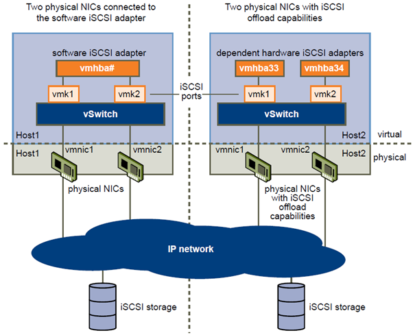
The iSCSI adapter and physical NIC connect through a virtual VMkernel adapter, also called virtual network adapter or VMkernel port. You create a VMkernel adapter (vmk) on a vSphere switch (vSwitch) using 1:1 mapping between each virtual and physical network adapter.
One way to achieve the 1:1 mapping when you have multiple NICs, is to designate a separate vSphere switch for each virtual-to-physical adapter pair. The following examples show configurations that use vSphere standard switches, but you can use distributed switches as well. For more information about vSphere distributed switches, see the vSphere Networking documentation.
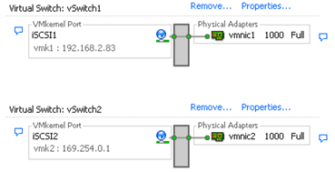
NOTE If you use separate vSphere switches, you must connect them to different IP subnets. Otherwise, VMkernel adapters might experience connectivity problems and the host will fail to discover iSCSI LUNs.
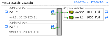
An alternative is to add all NICs and VMkernel adapters to a single vSphere standard switch. In this case, you must override the default network setup and make sure that each VMkernel adapter maps to only one corresponding active physical adapter.
The following table summarises the iSCSI networking configuration discussed in this topic.
| iSCSI Adapters | VMkernel Adapters (Ports) | Physical Adapters (NICs) |
| Software iSCSI | ||
| Vmhba32 | Vmk1 vmk2 |
Vmnic1 vmnic2 |
| Dependent Hardware iSCSI | ||
| Vmhba33 | Vmk1 | Vmnic1 |
| Vmhba34 | Vmk2 | vmnic2 |
Create Network Connections for iSCSI
Configure connections for the traffic between the software or dependent hardware iSCSI adapters and the physical network adapters.
The following tasks discuss the iSCSI network configuration with a vSphere standard switch.
If you use a vSphere distributed switch with multiple uplink ports, for port binding, create a separate distributed port group per each physical NIC. Then set the team policy so that each distributed port group has only one active uplink port. For detailed information on vSphere distributed switches, see the vSphere Networking documentation.
Procedure
- Create a Single VMkernel Adapter for iSCSI on page 78
You must connect the VMkernel, which runs services for iSCSI storage, to a physical network adapter. - Create Additional VMkernel Adapters for iSCSI on page 79
Use this task if you have two or more physical network adapters for iSCSI and you want to connect all of your NICs to a single vSphere standard switch. In this task, you add NICs and VMkernel adapters to an existing vSphere standard switch. - Change Port Group Policy for iSCSI VMkernel Adapters on page 80
If you use a single vSphere standard switch to connect VMkernel to multiple network adapters, change the port group policy, so that it is compatible with the iSCSI network requirements. - Bind iSCSI Adapters with VMkernel Adapters on page 80
Bind an iSCSI adapter with a VMkernel adapter.
Create a Single VMkernel Adapter for iSCSI
You must connect the VMkernel, which runs services for iSCSI storage, to a physical network adapter.
Procedure
- Log in to the vSphere Client, and select a host from the inventory panel.
- Click the Configuration tab and click Networking.
- In the vSphere Standard Switch view, click Add Networking.
- Select VMkernel and click Next.
- Select Create a vSphere standard switch to create a new standard switch.
- Select a NIC to use for iSCSI traffic.
IMPORTANT If you are creating a VMkernel interface for the dependent hardware iSCSI adapter, select the NIC that corresponds to the iSCSI component. See “Determine Association Between iSCSI and Network Adapters,” on page 74. - Click Next.
- Enter a network label.
A network label is a friendly name that identifies the VMkernel adapter that you are creating, for example, iSCSI. - Click Next.
- Specify the IP settings and click Next.
- Review the information and click Finish.
You created the virtual VMkernel adapter for a physical network adapter on your host.
What to do next
If your host has one physical network adapter for iSCSI traffic, you must bind the virtual adapter that you created to the iSCSI adapter.
If you have multiple network adapters, create additional VMkernel adapters and then perform iSCSI binding.
The number of virtual adapters must correspond to the number of physical adapters on the host.
Create Additional VMkernel Adapters for iSCSI
Use this task if you have two or more physical network adapters for iSCSI and you want to connect all of your NICs to a single vSphere standard switch. In this task, you add NICs and VMkernel adapters to an existing vSphere standard switch.
Prerequisites
You must create a vSphere standard switch that maps an iSCSI VMkernel adapter to a single physical NIC designated for iSCSI traffic.
Procedure
- Log in to the vSphere Client, and select a host from the inventory panel.
- Click the Configuration tab and click Networking.
- Select the vSphere standard switch that you use for iSCSI and click Properties.
-
Connect additional network adapters to the standard switch.
- In the standard switch Properties dialog box, click the Network Adapters tab and click Add.
- Select one or more NICs from the list and click Next.
With dependent hardware iSCSI adapters, select only those NICs that have a corresponding iSCSI component. - Review the information on the Adapter Summary page and click Finish.
The list of network adapters reappears, showing the network adapters that the vSphere standard switch now claims.
-
Create iSCSI VMkernel adapters for all NICs that you added.
The number of VMkernel interfaces must correspond to the number of NICs on the vSphere standard switch.- In the standard switch Properties dialog box, click the Ports tab and click Add.
- Select VMkernel and click Next.
- Under Port Group Properties, enter a network label, for example iSCSI, and click Next.
- Specify the IP settings and click Next.
When you enter the subnet mask, make sure that the NIC is set to the subnet of the storage system it connects to. - Review the information and click Finish.
CAUTION If the NIC you use with your iSCSI adapter, either software or dependent hardware, is not in the same subnet as your iSCSI target, your host cannot establish sessions from this network adapter to the target.
What to do next
Change the network policy for all VMkernel adapters, so that it is compatible with the network binding requirements. You can then bind the iSCSI VMkernel adapters to the software iSCSI or dependent hardware iSCSI adapters.
Change Port Group Policy for iSCSI VMkernel Adapters
If you use a single vSphere standard switch to connect VMkernel to multiple network adapters, change the port group policy, so that it is compatible with the iSCSI network requirements.
By default, for each virtual adapter on the vSphere standard switch, all network adapters appear as active. You must override this setup, so that each VMkernel interface maps to only one corresponding active NIC. For example, vmk1 maps to vmnic1, vmk2 maps to vmnic2, and so on.
Prerequisites
Create a vSphere standard switch that connects VMkernel with physical network adapters designated for iSCSI traffic. The number of VMkernel adapters must correspond to the number of physical adapters on the vSphere standard switch.
Procedure
- Log in to the vSphere Client and select the host from the inventory panel.
- Click the Configuration tab and click Networking.
- Select the vSphere standard switch that you use for iSCSI and click Properties.
- On the Ports tab, select an iSCSI VMkernel adapter and click Edit.
- Click the NIC Teaming tab and select Override switch failover order.
- Designate only one physical adapter as active and move all remaining adapters to the Unused Adapters category.
- Repeat Step 4 through Step 6 for each iSCSI VMkernel interface on the vSphere standard switch.
What to do next
After you perform this task, bind the virtual VMkernel adapters to the software iSCSI or dependent hardware iSCSI adapters.
Bind iSCSI Adapters with VMkernel Adapters
Bind an iSCSI adapter with a VMkernel adapter.
Prerequisites
Create a virtual VMkernel adapter for each physical network adapter on your host. If you use multiple VMkernel adapters, set up the correct network policy.
Required privilege: Host.Configuration.Storage Partition Configuration
Procedure
- Log in to the vSphere Client, and select a host from the inventory panel.
- Click the Configuration tab, and click Storage Adapters in the Hardware panel.
The list of available storage adapters appears. - Select the software or dependent iSCSI adapter to configure and click Properties.
- In the iSCSI Initiator Properties dialog box, click the Network Configuration tab.
- Click Add and select a VMkernel adapter to bind with the iSCSI adapter.
You can bind the software iSCSI adapter to one or more VMkernel adapters. For a dependent hardware iSCSI adapter, only one VMkernel interface associated with the correct physical NIC is available. - Click OK.
The network connection appears on the list of VMkernel port bindings for the iSCSI adapter. - Verify that the network policy for the connection is compliant with the binding requirements.
Managing iSCSI Network
Special consideration apply to network adapters, both physical and VMkernel, that are associated with an iSCSI adapter.
After you create network connections for iSCSI, an iSCSI indicator on a number of Networking dialog boxes becomes enabled. This indicator shows that a particular virtual or physical network adapter is iSCSI-bound.
To avoid disruptions in iSCSI traffic, follow these guidelines and considerations when managing iSCSI-bound virtual and physical network adapters:
- Make sure that the VMkernel network adapters are assigned addresses on the same subnet as the iSCSI storage portal they connect to.
- iSCSI adapters using VMkernel adapters are not able to connect to iSCSI ports on different subnets, even if those ports are discovered by the iSCSI adapters.
- When using separate vSphere switches to connect physical network adapters and VMkernel adapters, make sure that the vSphere switches connect to different IP subnets.
- If you migrate VMkernel adapters to a different vSphere switch, move associated physical adapters.
- Do not make configuration changes to iSCSI-bound VMkernel adapters or physical network adapters.
- Do not make changes that might break association of VMkernel adapters and physical network adapters.
You can break the association if you remove one of the adapters or the vSphere switch that connects them, or change the 1:1 network policy for their connection.
Other exam notes
- The Saffageek VCAP5-DCA Objectives http://thesaffageek.co.uk/vcap5-dca-objectives/
- Paul Grevink The VCAP5-DCA diaries http://paulgrevink.wordpress.com/the-vcap5-dca-diaries/
- Edward Grigson VCAP5-DCA notes http://www.vexperienced.co.uk/vcap5-dca/
- Jason Langer VCAP-DCA notes http://www.virtuallanger.com/vcap-dca-5/
-
The Foglite VCAP5-DCA notes http://thefoglite.com/vcap-dca5-objective/
VMware vSphere official documentation
| VMware vSphere Basics Guide | html | epub | mobi | |
| vSphere Installation and Setup Guide | html | epub | mobi | |
| vSphere Upgrade Guide | html | epub | mobi | |
| vCenter Server and Host Management Guide | html | epub | mobi | |
| vSphere Virtual Machine Administration Guide | html | epub | mobi | |
| vSphere Host Profiles Guide | html | epub | mobi | |
| vSphere Networking Guide | html | epub | mobi | |
| vSphere Storage Guide | html | epub | mobi | |
| vSphere Security Guide | html | epub | mobi | |
| vSphere Resource Management Guide | html | epub | mobi | |
| vSphere Availability Guide | html | epub | mobi | |
| vSphere Monitoring and Performance Guide | html | epub | mobi | |
| vSphere Troubleshooting | html | epub | mobi | |
| VMware vSphere Examples and Scenarios Guide | html | epub | mobi |
Disclaimer.
The information in this article is provided “AS IS” with no warranties, and confers no rights. This article does not represent the thoughts, intentions, plans or strategies of my employer. It is solely my opinion.