Knowledge
- Identify vCLI commands and tools used to troubleshoot vSphere networking configurations
- Identify logs used to troubleshoot network issues
Skills and Abilities
- Utilize net-dvs to troubleshoot vNetwork Distributed Switch configurations
- Utilize vSphere CLI commands to troubleshoot ESXi network configurations
- Troubleshoot Private VLANs
- Troubleshoot vmkernel related network configuration issues
- Troubleshoot DNS and routing related issues
- Use esxtop/resxtop to identify network performance problems
- Analyze troubleshooting data to determine if the root cause for a given network problem originates in the physical infrastructure or vSphere environment
- Configure and administer Port Mirroring
- Utilize Direct Console User Interface (DCUI) and ESXi Shell to troubleshoot, configure, and monitor ESXi networking
Utilize net-dvs to troubleshoot vNetwork Distributed Switch configurations
Official Documentation:
Available to administrators from only the ESXi Shell with root level access, the net-dvs command displays information about your distributed switch configuration.
Note that net-dvs is only supported for displaying information about your distributed switches. If you type net-dvs -help, you will be greeted with a warning, “Warning: This is an unsupported command. Use at your own risk.”
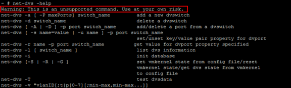
The net-dvs command will show you A LOT of information about your distributed switches. Probably a lot more then you want. By simply running net-dvs without any options or switches you’ll see the following information:
- Maximum ports
- The switch name
- Number of uplinks and their names
- MTU, Discovery protocol
- Individual configuration for each uplink, and its port numbers
Utilize vSphere CLI commands to troubleshoot ESXi network configurations
Official Documentation:
vSphere Command-Line Interface Concepts and Examples, Chapter 9 “Managing vSphere Networking”, page 109.
The vSphere CLI networking commands allow you to manage the vSphere network services. You can connect virtual machines to the physical network and to each other and configure vSphere standard switches. Limited configuration of vSphere distributed switches is also supported. You can also set up your vSphere environment to work with external networks such as SNMP or NTP.
Retrieving Basic Networking Information
Service console commands for retrieving networking information are not included in the ESXi Shell. You can instead use ESXCLI commands directly in the shell or use vCLI commands.
On ESXi 5.0, ifconfig information should be the information of the VMkernel NIC that attaches to the Management Network port group. You can retrieve information by using ESXCLI commands.
esxcli <conn_options> network ip interface list
esxcli <conn_options> network ip interface ipv4 get -n vmk<X>
esxcli <conn_options> network ip interface ipv6 get -n vmk<X>
esxcli <conn_options> network ip interface ipv6 address list
For information corresponding to the Linux netstat command, use the following ESXCLI command.
esxcli <conn_options> network ip connection list
Setting Up vSphere Networking with vSphere Standard Switches
You can set up your virtual network by performing these tasks.
- Create or manipulate virtual switches using esxcli network vswitch or vicfg-vswitch. By default, each ESXi host has one virtual switch, vSwitch0. You can create additional virtual switches or manage existing switches. See “Setting Up Virtual Switches and Associating a Switch with a Network Interface” on page 112.
- (Optional) Make changes to the uplink adapter using esxcli network vswitch standard uplink or vicfg-nics. See “Managing Uplink Adapters” on page 117.
- (Optional) Use esxcli network vswitch standard portgroup or vicfg-vswitch to add port groups to the virtual switch. See “Managing Port Groups with vicfg‐vswitch” on page 115.
- (Optional) Use esxcli network vswitch standard portgroup set or vicfg-vswitch to establish VLANs by associating port groups with VLAN IDs. See “Setting the Port Group VLAN ID with vicfg‐vswitch” on page 116.
- Use esxcli network ip interface or vicfg-vmknic to configure the VMkernel network interfaces. See “Adding and Modifying VMkernel Network Interfaces” on page 119.
Retrieving Information about Virtual Switches with ESXCLI
You can retrieve information about virtual switches by using esxcli network vswitch commands.
- List all virtual switches and associated port groups.
esxcli <conn_options> network vswitch standard list
The command prints information about the virtual switch, which might include its name, number of ports, MTU, port groups, and other information. The output includes information about CDP settings for the virtual switch. The precise information depends on the target system. The default port groups are Management Network and VM Network. - List the network policy settings (security policy, traffic shaping policy, and failover policy) for the virtual switch. The following commands are supported.
esxcli <conn_options> network vswitch standard policy failover get
esxcli <conn_options> network vswitch standard policy security get
esxcli <conn_options> network vswitch standard policy shaping get
Adding and Deleting Virtual Switches with ESXCLI
You can add and delete virtual switches using the esxcli network vswitch standard namespace. Specify one of the options listed in “Connection Options” on page 17 in place of <conn_options>.
- Add a virtual switch.
esxcli <conn_options> network vswitch standard add –vswitch-name=vSwitch42
You can specify the number of port groups while adding the virtual switch. If you do not specify a value, the default value is used. The system‐wide port count cannot be greater than 4096.
esxcli <conn_options> network vswitch standard add –vswitch-name=vSwitch42 –ports=8 - Delete a virtual switch.
esxcli <conn_options> network vswitch standard remove –vswitch-name=vSwitch42
You cannot delete a virtual switch if any ports on the switch are still in use by VMkernel networks or virtual machines. Run esxcli network vswitch standard list to determine whether a virtual switch is in use.
Setting Switch Attributes with esxcli network vswitch standard
You can set the maximum transmission unit (MTU) and CDP status for a virtual switch. The CDP status shows which Cisco switch port is connected to which uplink. Specify one of the options listed in “Connection Options” on page 17 in place of <conn_options>.
- Set the MTU for a vSwitch.
esxcli <conn_options> network vswitch standard set –mtu=9000 –vswitch-name=vSwitch1
The MTU is the size, in bytes, of the largest protocol data unit the switch can process. When you set this option, it affects all uplinks assigned to the virtual switch. - Set the CDP value for a vSwitch. You can set status to down, listen, advertise, or both.
esxcli <conn_options> network vswitch standard set –cdp-status=listen –vswitch-name=vSwitch1
Managing Port Groups with ESXCLI
Network services connect to vSwitches through port groups. A port group allows you to group traffic and specify configuration options such as bandwidth limitations and VLAN tagging policies for each port in the port group. A virtual switch must have one port group assigned to it. You can assign additional port groups.
You can use esxcli network vswitch standard portgroup to check, add, and remove port groups. Specify one of the options listed in “Connection Options” on page 17 in place of <conn_options>.
- List port groups currently associated with a virtual switch.
esxcli <conn_options> network vswitch standard portgroup list
Lists the port group name, associated virtual switch, active clients, and VLAN ID. - Add a port group.
esxcli <conn_options> network vswitch standard portgroup add –portgroup-name=<name> –vswitch-name=vSwitch1 - Delete one of the existing port groups.
esxcli <conn_options> network vswitch standard portgroup remove –portgroup-name=<name> –vswitch-name=vSwitch1
Connecting and Disconnecting Uplink Adapters and Port Groups with ESXCLI
If your setup includes one or more port groups, you can associate each port group with one or more uplink adapters (and remove the association). This functionality allows you to filter traffic from a port group to a specific uplink, even if the virtual switch is connected with multiple uplinks. Specify one of the options listed in “Connection Options” on page 17 in place of <conn_options>.
- Connect a port group with an uplink adapter.
esxcli <conn_options> network vswitch standard portgroup policy failover set –active-uplinks=vmnic1,vmnic6,vmnic7
This command fails silently if the uplink adapter does not exist. - Make some of the adapters standby instead of active.
esxcli <conn_options> network vswitch standard portgroup policy failover set –standby-uplinks=vmnic1,vmnic6,vmnic7
Setting the Port Group VLAN ID with ESXCLI
VLANs allow you to further segment a single physical LAN segment so that groups of ports are isolated as if they were on physically different segments. The standard is IEEE 802.1Q.
A VLAN ID restricts port group traffic to a logical Ethernet segment within the physical network.
- Set the VLAN ID to 4095 to allow a port group to reach port groups located on other VLAN.
- Set the VLAN ID to 0 to disable the VLAN for this port group.
If you use VLAN IDs, you must change the port group labels and VLAN IDs together so that the labels properly represent connectivity. VLAN IDs are optional.
You can use the following commands for VLAN management:
- Allow port groups to reach port groups located on other VLANs.
esxcli <conn_options> network vswitch standard portgroup set -p <pg_name> –vlan-id 4095
Call the command multiple times to allow all ports to reach port groups located on other VLANs. - Disable VLAN for port group g42
esxcli <conn_options> network vswitch standard portgroup set –vlan-id 0 -p <pg_name>
Managing Uplink Adapters with esxcli network nic
The following example workflow lists all uplink adapters, lists properties for one uplink adapter, changes the uplink’s speed and duplex settings, and brings the uplink down and back up. Specify one of the options listed in “Connection Options” on page 17 in place of <conn_options>.
To manipulate uplink adapter setup
- List all uplinks and information about each device.
esxcli <conn_options> network nic list
You can narrow down the information displayed by using esxcli network nic get –nic-name=<nic>. - (Optional) Bring down one of the uplink adapters.
esxcli <conn_options> network nic down –nic-name=vmnic0 - Change uplink adapter settings.
esxcli <conn_options> network nic set <option>
Specify one of the following options.
| -a|–auto | Set the speed and duplex settings to autonegotiate. |
| -D|–duplex=<str> | Duplex to set this NIC to. Acceptable values are full and half. |
| -P | –phy-address | Set the MAC address of the device |
| -l|–message-level=<long> | Set the driver message level. Message levels and what they imply differ perdriver. |
| -n|–nic-name=<str> | Name of the NIC to configured. Must be one of the cards listed in the nic listcommand (required). |
| -p|–port=<str> | Selects the device port. The following device ports are available.
|
| -S|–speed=<long> | Speed to set this NIC to. Acceptable values are 10, 100, 1000, and 10000. |
| -t|–transceiver-type=<str> | Select transceiver type. The following transceiver types are available.
|
| -w|–wake-on-lan=<str> | Set Wake-on-LAN options. Not all devices support this option. The option valueis a string of characters specifying which options to enable.
|
-
(Optional) Bring the uplink adapter back up.
esxcli <conn_options> network nic up –nic-name=vmnic0
Specifying Multiple Uplinks with ESXCLI
At any time, one port group NIC array and a corresponding set of active uplinks exist. When you change the active uplinks, you also change the standby uplinks and the number of active uplinks.
The following example illustrates how active and standby uplinks are set.
- The portgroup nic array is [vmnic1, vmnic0, vmnic3, vmnic5, vmnic6, vmnic7] and active-uplinks is set to three uplinks (vmnic1, vmnic0, vmnic3). The other uplinks are standby uplinks.
- You set the active uplinks to a new set [vmnic3, vmnic5].
- The new uplinks override the old set. The NIC array changes to [vmnic3, vmnic5, vmnic6, vmnic7]. vmnic0 and vmnic1 are removed from the NIC array and max-active becomes 2.
If you want to keep vmnic0 and vmnic1 in the array, you can make those NICs standby uplinks in the command that changes the active uplinks.
esxcli network vswitch standard portgroup policy failover set -p testPortgroup –active-uplinks vmnic3,vmnic5 –standby-uplinks vmnic1,vmnic0,vmnic6,vmnic7
Linking and Unlinking Uplink Adapters with ESXCLI
When you create a virtual switch using esxcli network vswitch standard add, all traffic on that virtual switch is initially confined to that virtual switch. All virtual machines connected to the virtual switch can talk to each other, but the virtual machines cannot connect to the network or to virtual machines on other hosts. A virtual machine also cannot connect to virtual machines connected to a different virtual switch on the same host.
Having a virtual switch that is not connected to the network might make sense if you want a group of virtual machines to be able to communicate with each other, but not with other hosts or with virtual machines on other hosts. In most cases, you set up the virtual switch to transfer data to external networks by attaching one or more uplink adapters to the virtual switch.
You can use the following commands to list, add, and remove uplink adapters:
- List uplink adapters.
esxcli <conn_options> network vswitch standard list
The uplink adapters are returned in the Uplink item. - Add a new uplink adapter to a virtual switch.
esxcli <conn_options> network vswitch standard uplink add –uplink-name=vmnic15 vswitch-name=vSwitch0 - Remove an uplink adapter from a virtual switch.
esxcli <conn_options> network vswitch standard uplink remove –uplink-name=vmnic15 vswitch-name=vSwitch0
Managing VMkernel Network Interfaces with ESXCLI
You can configure the VMkernel network interface for IPv4 (see “To add and configure an IPv4 Vmkernel Network Interface for IPv4” on page 120) or for IPv6 (see “To add and configure a VMkernel Network Interface for IPv6” on page 120) with ESXCLI. In contrast to vicfg-vmknic, ESXCLI does not support enabling vMotion.
You can add and configure an IPv4 VMkernel NIC with ESXCLI. Specify one of the options listed in “Connection Options” on page 17 in place of <conn_options>.
To add and configure an IPv4 VMkernel Network Interface for IPv4
- Add a new VMkernel network interface.
esxcli <conn_options> network ip interface add –interface-name=vmk<x> –portgroup-name=<my_portgroup>
You can specify the MTU setting after you have added the network interface by using esxcli network ip interface set –mtu. -
Configure the interface as an IPv4 interface. You must specify the IP address using –ip, the netmask, and the name. For the following examples, assume that VMSF‐VMK‐363 is a port group to which you want to add a VMkernel network interface.
esxcli <conn_options> network ip interface ipv4 set –ip=<ip_address> –netmask=255.255.255.0 –interface-name=vmk<X>
You can set the address as follows.- <X.X.X.X>– Static IPv4 address.
- DHCP – Use IPv4 DHCP.
The VMkernel supports DHCP only for ESXi 4.0 and later.
When the command finishes successfully, the newly added VMkernel network interface is enabled.
- List information about all VMkernel network interfaces on the system.
esxcli <conn_options> network ip interface list
The command displays the network information, port group, MTU, and current state for each virtual network adapter in the system.
You can add and configure an IPv6 VMkernel NIC with ESXCLI.
To add and configure a VMkernel Network Interface for IPv6
- Run esxcli network ip interface add to add a new VMkernel network interface.
esxcli <conn_options> network ip interface add –interface-name=vmk<x> –portgroup-name=<my_portgroup>
You can specify the MTU setting after you have added the network interface by using esxcli network ip interface set –mtu.
When the command finishes successfully, the newly added VMkernel network interface is enabled. -
Run esxcli network ip interface ipv6 address add to configure the interface as an IPv6 interface.
You must specify the IP address using –ip and the name. For the following examples, assume that VMSF‐VMK‐363 is a port group to which you want to add a VMkernel network interface.
esxcli <conn_options> network ip interface ipv6 address add –ip=<X:X:X::/X> –interface-name=vmk<X>
You can set the address as follows.- <X:X:X::/X>: Static IPv6 address
- –enable-dhcpv6: Enables DHCPv6 on this interface and attempts to acquire an IPv6 address from the network.
- –enable-router-adv: Use the IPv6 address advertised by the router. The address is added when the router sends the next router advert.
The VMkernel supports DHCP only for ESXi 4.0 and later.
When the command completes successfully, the newly added VMkernel network interface is enabled.
- List information about all VMkernel network interfaces on the system.
esxcli <conn_options> network ip interface list
The list contains the network information, port group, MTU, and current state for each Vmkernel Network Interface on the system. -
You can later remove the IPv6 address and disable IPv6.
esxcli <conn_options> network ip interface ipv6 address remove –interface-name=<VMK_NIC> –ipv6=<ipv6_addr>esxcli <conn_options> network ip set –ipv6-enabled=false
Troubleshoot Private VLANs
Official Documentation:
vSphere Networking, Chapter 3 “Setting up Networking with vSphere Distributed Switches”, Section “Private VLANs”, page 27.
Private VLANs have been discussed in Objective 2.2 – Configure and Maintain VLANs, PVLANs and VLAN Settings
Troubleshoot vmkernel related network configuration issues
Official Documentation:
First place to look is the vmkernel log file, located on every host at /var/log/vmkernel.log. This will present any events related to networking configuration and the vmkernel.
Ensure you have at least one vmkernel interface enabled for management. You should have at least two vmkernel interfaces on different networks plugged into separate switches for redundancy
Use vicfg-vmknic to assist in configuration validation as well as the vSphere Client/Web Client
Use the DCUI to test management networking connectivity
You can also use esxcli network diag ping to troubleshoot connectivity
Troubleshoot DNS and routing related issues
Official Documentation:
vSphere Command-Line Interface Concepts and Examples, Chapter 9 “Managing vSphere Networking”, section “Setting the DNS Configuration”, page 123.
Setting the DNS Configuration with ESXCLI
The esxcli network ip dns command lists and specifies the DNS configuration of your ESXi host.
IMPORTANT If you try to change the host or domain name or the DNS server on hosts that use DHCP, an error results.
In network environments where a DHCP server and a DNS server are available, ESXi hosts are automatically assigned DNS names.
In network environments where automatic DNS is not available or you do not want to use automatic DNS, you can configure static DNS information, including a host name, primary name server, secondary name server, and DNS suffixes.
The esxcli network ip dns namespace includes two namespaces.
- esxcli network ip dns search includes commands for DNS search domain configuration.
- esxcli network ip dns server includes commands for DNS server configuration.
The following example illustrates setting up a DNS server. Specify one of the options listed in “Connection Options” on page 17 in place of <conn_options>.
To set up a DNS Server
- Print a list of DNS servers configured on the system in the order in which they will be used.
esxcli <conn_options> network ip dns server list
If DNS is not set up for the target server, the command returns an empty string. - Add a server by running esxcli network ip dns server add and specifying the server IPv4 address or IPv6 address.
esxcli <conn_options> network ip dns server add –server=<str> -
Change the settings with esxcli network ip dns.
- Specify the DNS server using the –dns option and the DNS host.
esxcli <conn_options> network ip dns server add –server=<server>
Run the command multiple times to specify multiple DNS hosts. - Configure the DNS host name for the server specified by –server (or –vihost).
esxcli <conn_options> system hostname set –host=<new_host_name> - Configure the DNS domain name for the server specified by –server (or –vihost).
esxcli <conn_options> system hostname –domain=mydomain.biz
- Specify the DNS server using the –dns option and the DNS host.
-
To turn on DHCP, enable DHCP and set the VMkernel NIC.
- Turn on DHCP for IPv4
esxcli <conn_options> network ip interface ipv4 set –type dhcp/none/static
esxcli <conn_options> network ip interface ipv4 set –peer-dns=<str> - Turn on DHCP for IPv6
esxcli <conn_options> network ip interface ipv6 set –enable-dhcpv6=true/false
esxcli <conn_options> network ip interface ipv6 set –peer-dns=<str>
- Turn on DHCP for IPv4
To modify DNS setup for a preconfigured server
-
Display DNS properties for the specified server as follows:
- List the host and domain name.
esxcli <conn_options> system hostname get - List available DNS servers
esxcli <conn_options> network ip dns server list - List the DHCP settings for individual VMkernel NICs.
esxcli <conn_options> network ip interface ipv4 get
esxcli <conn_options> network ip interface ipv6 get
- List the host and domain name.
-
If the DNS properties are set, and you want to change the DHCP settings, you must specify the virtual network adapter to use when overriding the system DNS. Override the existing DHCP setting as follows:
esxcli <conn_options> network ip interface ipv4 set –type dhcp/none/static
esxcli <conn_options> network ip interface ipv6 set –enable-dhcpv6=true/false
Managing the IP Gateway
If you move your ESXi host to a new physical location, you might have to change the default IP gateway. You can use the vicfg-route command to manage the default gateway for the VMkernel IP stack. vicfg-route supports a subset of the Linux route command’s options.
IMPORTANT No ESXCLI command exists to manage the default gateway
If you run vicfg-route with no options, the command displays the default gateway. Use –family to print the default IPv4 or the default IPv6 gateway. By default, the command displays the default IPv4 gateway. Specify one of the options listed in “Connection Options” on page 17 in place of <conn_options>.
To add, view, and delete a route entry
-
Add a route entry to the VMkernel and make it the default.
- For IPv4 networks, no additional options are required.
vicfg-route <conn_options> –add <network_ip> <netmask_IP> <gateway_ip>
For example, to add a route to 192.XXX.100.0 through 192.XXX.0.1:
vicfg-route <conn_options> -a 192.XXX.100.0/24 192.XXX.0.1
or
vicfg-route <conn_options> -a 192.XXX.100.0 255.255.255.0 192.XXX.0.1 - For IPv6 networks, use –family v6
vicfg-route <conn_options> -f V6 –add <network_ip_and_mask> <gateway_ip>
For example:
vicfg-route <conn_options> -f V6 –add 2001:10:20:253::/64 2001:10:20:253::1
- For IPv4 networks, no additional options are required.
- List route entries to check that your route was added by running the command without options.
vicfg-route <conn_options>
The output lists all networks and corresponding netmasks and gateways. -
Set the default gateway.
- For IPv4, use this syntax:
vicfg-route <conn_options> 192.XXX.0.1
or
vicfg-route <conn_options> -a default 192.XXX.0.1 - For IPv6, use this syntax:
vicfg-route <conn_options> -f V6 -a default 2001:10:20:253::1
- For IPv4, use this syntax:
- Run vicfg-route –delete to delete the route. Specify first the gateway, and then the network.
vicfg-route <conn_options> -d 192.XXX.100.0/24 192.XXX.0.1
Use esxtop/resxtop to identify network performance problems
Official Documentation:
It’s not an official document, but very usefull. vSphere 5 ESXTOP quick Overview for Troubleshooting http://www.vmworld.net/wp-content/uploads/2012/05/Esxtop_Troubleshooting_eng.pdf
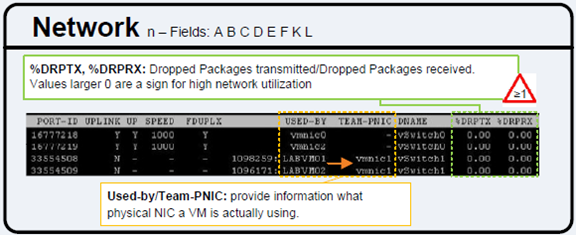
See the Network section.
%DRPTX, %DRPRX: Dropped Packages transmitted/Dropped Packages received.
Values larger 0 are a sign for high network utilization
Analyze troubleshooting data to determine if the root cause for a given network problem originates in the physical infrastructure or vSphere environment
Official Documentation:
General recommendations for troubleshooting virtual network troubleshooting:
- Start Bottom-up instead of Top Down;
- Start with physical Layer (L1) of the OSI Model and work your way up.
- Know the concepts of Standard switches and Distributed switches.
Understand the difference between VM portgroups and VMkernel Portgroups.
Know how to configure VMkernel Portgroups.
Understand physical uplinks, NIC teaming and Security settings.
Physical NICs are connected to physical switches.
Know how switch ports are configured, access port, trunk port, which VLANs are allowed. - dvSwitches can standardize configurations across all hosts but also complicate troubleshooting.
- Avoid the urge to reboot and continue searching for the root cause (your evidence has usually gone after a reboot.
Configure and administer Port Mirroring
Official Documentation:
vSphere Networking, Chapter 6 “Advanced Networking”, Section “Working with Port Mirroring”, page 68.
Port mirroring allows you to mirror a distributed port’s traffic to other distributed ports or specific physical switch ports.
Create a Port Mirroring Session
Create a port mirroring session to mirror vSphere distributed switch traffic to specific physical switch ports.
Prerequisites
Create a vSphere distributed switch version 5.0.0 or later.
Procedure
- Specify Port Mirroring Name and Session Details on page 69. Specify the name, description, and session details for the new port mirroring session.
- Choose Port Mirroring Sources on page 69. Select sources and traffic direction for the new port mirroring session.
- Choose Port Mirroring Destinations on page 69. Select ports, or uplinks as destinations for the port mirroring session.
- Verify New Port Mirroring Settings on page 70. Verify and enable the new port mirroring session.
Specify Port Mirroring Name and Session Details
Specify the name, description, and session details for the new port mirroring session.
Procedure
- Log in to the vSphere Client and select the Networking inventory view.
- Right-click the vSphere distributed switch in the inventory pane, and select Edit Settings.
- On the Port Mirroring tab, clickAdd.
- Enter a Name and Description for the port mirroring session.
- (Optional) Select Allow normal IO on destination ports to allow normal IO traffic on destination ports.
If you do not select this option, mirrored traffic will be allowed out on destination ports, but no traffic will be allowed in. - (Optional) Select Encapsulation VLAN to create a VLAN ID that encapsulates all frames at the destination ports.
If the original frames have a VLAN and Preserve original VLAN is not selected, the encapsulation VLAN replaces the original VLAN. - (Optional) Select Preserve original VLAN to keep the original VLAN in an inner tag so mirrored frames are double encapsulated.
This option is available only if you select Encapsulation VLAN. - (Optional) Select Mirrored packet length to put a limit on the size of mirrored frames.
If this option is selected, all mirrored frames are truncated to the specified length. - Click Next.
Choose Port Mirroring Sources
Select sources and traffic direction for the new port mirroring session.
Procedure
- Choose whether to use this source for Ingress or Egress traffic, or choose Ingress/Egress to use this source for both types of traffic.
- Type the source port IDs and click >> to add the sources to the port mirroring session.
Separate multiple port IDs with a comma. - Click Next.
Choose Port Mirroring Destinations
Select ports, or uplinks as destinations for the port mirroring session.
Port Mirroring is checked against the VLAN forwarding policy. If the VLAN of the original frames is not equal to or trunked by the destination port, the frames are not mirrored.
Procedure
- Choose the Source type.
| Option | Description |
| Port | Type in one or more Port IDs to use as a destination for the port mirroringsession. Separate multiple IDs with a comma. |
| Uplink | Select one or more uplinks to use as a destination for the port mirroringsession. |
- Click >> to add the selected destinations to the port mirroring session.
- (Optional) Repeat the above steps to add multiple destinations.
- Click Next.
Verify New Port Mirroring Settings
Verify and enable the new port mirroring session.
Procedure
- Verify that the listed name and settings for the new port mirroring session are correct.
- (Optional) Click Back to make any changes.
- (Optional) Click Enable this port mirroring session to start the port mirroring session immediately.
- Click Finish.
View Port Mirroring Session Details
View port mirroring session details, including status, sources, and destinations.
Procedure
- Log in to the vSphere Client and select the Networking inventory view.
- Right-click the vSphere distributed switch in the inventory pane, and select Edit Settings.
- On the Port Mirroring tab, select the port mirroring session to view.
Details for the selected port mirroring session appear under Port Mirroring Session Details. - (Optional) Click Edit to edit the details for the selected port mirroring session.
- (Optional) Click Delete to delete the selected port mirroring session.
- (Optional) Click Add to add a new port mirroring session.
Edit Port Mirroring Name and Session Details
Edit the details of a port mirroring session, including name, description, and status.
Procedure
- Log in to the vSphere Client and select the Networking inventory view.
- Right-click the vSphere distributed switch in the inventory pane, and select Edit Settings.
- On the Port Mirroring tab, select the port mirroring session to modify and click Edit.
- Click the Properties tab.
- (Optional) Type a new Name for the port mirroring session.
- (Optional) Type a new Description for the port mirroring session.
- Select whether the port mirroring session should be Enabledor Disabled.
- (Optional) Select Allow normal IO on destination ports to allow normal IO traffic on destination ports.
If you do not select this option, mirrored traffic is allowed out on destination ports, but no traffic is allowed in. - (Optional) Select Encapsulation VLAN to create a VLAN ID that encapsulates all frames at the destination ports.
If the original frames have a VLAN and Preserve original VLAN is not selected, the encapsulation VLAN replaces the original VLAN. - (Optional) Select Preserve original VLAN to keep the original VLAN in an inner tag so mirrored frames are double encapsulated.
This option is available only if you select Encapsulation VLAN. - (Optional) Select Mirrored packet length to put a limit on the size of mirrored frames.
If this option is selected, all mirrored frames are truncated to the specified length. - Click OK.
Edit Port Mirroring Sources
Edit sources and traffic direction for the port mirroring session.
Procedure
- Log in to the vSphere Client and select the Networking inventory view.
- Right-click the vSphere distributed switch in the inventory pane, and select Edit Settings.
- On the Port Mirroring tab, select the port mirroring session to modify and click Edit.
- Click the Sources tab.
- (Optional) Select whether to use this source for Ingress or Egress traffic, or select Ingress/Egress to use this source for both types of traffic.
- (Optional) Type one or more port IDs or ranges of port IDs to add as source for the port mirroring session, and click >>.
Separate multiple IDs with commas. - (Optional) Select a source in the right-hand list and click << to remove the source from the port mirroring session.
- Click OK.
Edit Port Mirroring Destinations
Edit the destination ports and uplinks for a port mirroring session to change where traffic for the session is mirrored.
Procedure
- Log in to the vSphere Client and select the Networking inventory view.
- Right-click the vSphere distributed switch in the inventory pane, and select Edit Settings.
- On the Port Mirroring tab, select the port mirroring session to modify and click Edit.
- Click the Destinations tab.
- (Optional) Select the Destination type of the destination to add.
| Option | Description |
| Port | Type one or more Port IDs to use as a destination for the port mirroring session. Separate multiple IDs with a comma. |
| Uplink | Select one or more uplinks to use as a destination for the port mirroringsession. |
- (Optional) Type one or more port IDs or ranges of port IDs to add as a destination for the port mirroring session and click >>.
Separate multiple IDs with commas. - (Optional) Select a destination from the right-hand column and click << to remove the destination from the port mirroring session.
- Click OK.
Utilize Direct Console User Interface (DCUI) and ESXi Shell to troubleshoot, configure, and monitor ESXi networking
Official Documentation:
There are three ways to get in to the DCUI interface of an ESXi host.
- Directly from the physical console.
- Remote Access Card (ILO, DRAC)
-
From an existing SSH session to an ESXi host, type: # DCUI
The DCUI offers you options for:
- Adjusting root password
- Configure, Restart an Test the Management network
- Restore Network Setting or even Restore a standard switch (very useful option, in case you have meshed up you vDS)
- Troubleshooting options, enabling SSH or the ESXi shell and restarting the Management Agents
- View the ESXi logging
- Finally, resetting the ESXi configuration to default settings!
Other exam notes
- The Saffageek VCAP5-DCA Objectives http://thesaffageek.co.uk/vcap5-dca-objectives/
- Paul Grevink The VCAP5-DCA diaries http://paulgrevink.wordpress.com/the-vcap5-dca-diaries/
- Edward Grigson VCAP5-DCA notes http://www.vexperienced.co.uk/vcap5-dca/
- Jason Langer VCAP5-DCA notes http://www.virtuallanger.com/vcap-dca-5/
- The Foglite VCAP5-DCA notes http://thefoglite.com/vcap-dca5-objective/
VMware vSphere official documentation
| VMware vSphere Basics Guide | html | epub | mobi | |
| vSphere Installation and Setup Guide | html | epub | mobi | |
| vSphere Upgrade Guide | html | epub | mobi | |
| vCenter Server and Host Management Guide | html | epub | mobi | |
| vSphere Virtual Machine Administration Guide | html | epub | mobi | |
| vSphere Host Profiles Guide | html | epub | mobi | |
| vSphere Networking Guide | html | epub | mobi | |
| vSphere Storage Guide | html | epub | mobi | |
| vSphere Security Guide | html | epub | mobi | |
| vSphere Resource Management Guide | html | epub | mobi | |
| vSphere Availability Guide | html | epub | mobi | |
| vSphere Monitoring and Performance Guide | html | epub | mobi | |
| vSphere Troubleshooting | html | epub | mobi | |
| VMware vSphere Examples and Scenarios Guide | html | epub | mobi |
Disclaimer.
The information in this article is provided “AS IS” with no warranties, and confers no rights. This article does not represent the thoughts, intentions, plans or strategies of my employer. It is solely my opinion.